background image


13 


Connecting Power Adapter and I/O Cables 

To have the terminal ready for operation, please connect the connector of 
power adapter and all of the connectors of required I/O cables respectively to 
the 12VDC-IN power jack and appropriate I/O ports. Please make sure that 
each of the cables is fully connected to each of the correct ports. Damages due 
to incorrect connection or orientation are not covered by product warranty! 

Some cable connectors like the connectors of the COM or LAN cables have to 
be gently inserted until a click is heard. It is recommended that the I/O ports, 
such as COM port, should be screwed after the I/O cable connectors are 
completely connected. And please make sure that each connector has to be 
connected to the right peripheral device in the right way. 


CAUTION: On doing insertion or extraction of a cable connector, please always hold the 
connector head itself instead of pulling the cable wire. Doing this could damage the cables 
and ports, which is considered as an artificial damage and is not covered by the warranty. 
The means of power cord should be connected to a socket-outlet with earthing connection. 

ATTENTION: Lors de l'insertion ou de l'extraction d'un connecteur de câble, veuillez 
toujours tenir la tête du connecteur elle-même au lieu de tirer le fil du câble. Cela pourrait 
endommager les câbles, ce qui est considéré comme un dommage artificiel et n'est pas 
couvert par la garantie. Le cordon d'alimentation doit être connecté à une prise de courant 
avec mise à la terre. 

Routing and Arranging Cables 

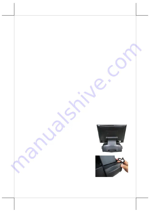
Gen 7E/8E bases feature their own cable management to help you well 
organize the cords whenever you need to connect peripheral devices to XT-
7315/7515. The following provides some useful cable-routing instructions 
required to manage your cables. 

1.


Set up your terminal in Full Extended 
mode and then tilt the screen all the way 
down. 


2.


Remove the cable cover.  


Summary of Contents for XT-7315

Page 1: ...ons 1 This device may not cause harmful interference and 2 this device must accept any interference received including interference that may cause undesired operation CE CLASS A WARNING This equipment is compliant with Class A of CISPR 32 In a residential environment this equipment may cause radio interference WARRANTY LIMITS Warranty will terminate automatically when the machine is opened by any ...

Page 2: ...RIE ATTENTION NOTES Jetez les piles usagées conformément aux instructions Remplacement d une batterie avec un type incorrect qui peut annuler une sauvegarde par exemple dans le cas de certains types de batterie au lithium Mise au rebut d une batterie dans le feu ou dans un four chaud ou écrasement ou coupure mécanique d une batterie pouvant entraî ner une explosion Laisser une batterie dans un env...

Page 3: ...View Bottom View Cable Holder Cable Exit Cable Cover Neck Cover Cable Exit Power Button Brightness Adjustment Button Brightness Adjustment Button Rubber Feet with Fixing Screw Rubber Feet with Fixing Screw HDD SSD Cover ...

Page 4: ...15 7515 with Gen 8E Base Front View Rear View Side View Cable Cover Neck Cover Cable Exit LED indicator Power Button Brightness Adjustment Button Brightness Adjustment Button Gen 8E Base HDD SSD Cover P CAP Touch Panel ...

Page 5: ... both bases provide three standard positioning solutions for your terminal Flat Folded mode Low Profile mode and Full Extended mode XT 7315 7515 with Gen 7E Base Flat Folded mode Low Profile mode Full Extended mode DC IN Power Connector USB 2 0 Ports USB 3 0 Ports VGA Port LAN Ports Line Out DB9 COM Ports RJ 50 COM Ports CR Port 12V BAT Port UPS Port Mini HDMI Port Rubber Feet with Fixing Screw UP...

Page 6: ...l not to touch the LCD panel while setting up the tilt angle XT 7315 7515 with Gen 7E Base Please refer to the following instructions on how to switch among different positioning modes to find an ideal viewing angle for XT 7315 7515 with Gen 7E base 1 Unpack XT 7315 7515 which is supposed to be set in flat folded mode out of the package box and then lay your POS system on a flat surface 2 Steady t...

Page 7: ... lever is snapped into the lower hook to raise the screen as shown in the below figure 3 3 With the screen facing toward you tilt the screen up or down to your desired angle Please do not press on the LCD panel while setting up the tilt angle 3 4 Remove the cable cover from the base 3 5 Fix the base with two 6 32 14L screws Lever Lower hook ...

Page 8: ...base 4 2 Remove the two screws from the base 4 3 Tilt your screen in a horizontal position 4 4 Support the screen with one hand holding onto its bottom edge While pulling the lever backwards move the display downwards until the lever is lifted off the hook as shown in the figure Remove the two screws Hook Lever ...

Page 9: ...esired angle please be advised to keep the base steady with one hand to do so Do NOT press on the LCD panel while setting up the tilt angle XT 7315 7515 with Gen 8E Base Please refer to the following instructions on how to switch among different positioning modes to find an ideal viewing angle for XT 7315 7515 with Gen 8E base 1 Unpack XT 7315 7515 which is supposed to be set in flat folded mode o...

Page 10: ... Support the screen with one hand holding onto its bottom edge Then while pulling the lever backwards move the display upwards until the lever is snapped into the lower hook to raise the screen as shown in the below figure 4 2 Tilt the screen up or down to your desired angle Please do not press on the LCD panel while setting up the tilt angle 4 3 Fix the base with two 6 32 14L screws Lower hook Le...

Page 11: ...inal down Then remove the cable cover from the base 5 2 Remove the two screws from the base 5 3 Support the screen with one hand holding onto its bottom edge Then while pulling the lever backwards move the display upwards or downwards until the lever is snapped into the upper hook to lower the screen as shown in the below figure Remove the two screws Lever Upper hook ...

Page 12: ... 6 1 While steadying your terminal with your hand holding onto the base tilt your screen up Remove the cable cover from the base 6 2 Support the screen with one hand holding onto its bottom edge While pulling the lever backwards release the lever back to the point above the upper hook as shown in the figure 6 3 Push the cable cover back 6 4 Tilt the screen to the horizontal position Lever Upper ho...

Page 13: ...e always hold the connector head itself instead of pulling the cable wire Doing this could damage the cables and ports which is considered as an artificial damage and is not covered by the warranty The means of power cord should be connected to a socket outlet with earthing connection ATTENTION Lors de l insertion ou de l extraction d un connecteur de câble veuillez toujours tenir la tête du conne...

Page 14: ...l up enough to have the bottom I O plate towards you Locate the cable arrangement cover as shown in the figure 6 Remove the cable arrangement cover by pushing it up in the direction shown by the arrow 7 Properly insert the cable into the correct port on the bottom I O plate 8 Neatly arrange your cable Then make sure the cord can be held into place and passed through the cable exit after sliding ba...

Page 15: ...t POS system with these optional upgrade kits Before proceeding with the installation of peripherals please make sure the POS system is completely shut down to prevent damage Installing UPS Battery to Gen 8E Base UPS battery compartment can be found at the bottom of Gen 8E base as shown in the figure Please be advised that the installation of UPS battery should be conducted by a technician accordi...

Page 16: ...r feet facing you Place the bottom side of the power adapter into the bottom of the power adapter compartment first and then push the top side of the adaptor into the compartment 3 After pushing the power adapter up to the top place two brackets separately on the top and bottom sides of the power adapter compartment as shown in the figure Then fasten two brackets with four fixing screws 4 Before t...

Page 17: ...le tie to hold the extra cable 2 as shown in the figure 7 Place back the PoweredUSB compartment bracket into place and then secure it using two fixing screws 8 Lay the POS terminal on a flat surface with its rear facing towards you Then connect the female end of power cord to the power adapter and the other end to the electrical outlet 9 To hold the power cord into place attach the screw hole of p...

Page 18: ...e user manual specific to the device you intend to install Installing Wall Mount Kits The wall mount kits enable you to mount your POS terminal onto the wall as an alternative Step A Select a flat surface on wall of adequate strength and thickness and with proper ventilation and space condition Step B To apply the plastic cotters please drill 4 holes in rectangular layout as marked in the template...

Page 19: ...lated working environment In doing so please be advised to keep the POS terminal at least 25mm away from other devices to ensure the machine is properly cooled down and functioning normally Powering ON OFF XT 7315 7515 Power ON XT 7315 7515 Press down the power button for at least 3 seconds to power on the POS Power OFF XT 7315 7515 In most cases press the power button of the POS to power the syst...

Page 20: ... Port Mini HDMI connector inside I O plate USB Port 6 ports 4 x USB 3 0 2 x USB 2 0 on I O plate 2 internal USB headers CR Port 1 port controlling 2 x CR with 24V support only COM1 COM5 control selectable dual CR detection support PS 2 Port Pin header inside service window LAN Port 2 x 10 100 1000 Mb Audio 1 x internal 2W speaker Line out Line out jack on I O plate UPS Port Yes Touch Controller US...

Reviews: