background image


Part 4 

VESA MOUNT


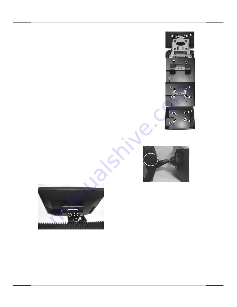
After releasing the stand’s back cover, please unfasten these 
two screws to remove the main structure of base stand 
which arrowed in the right picture. 


After that, please use flat drill to release the hinge cover 
from the arrowed side as show in the right picture. 


Next, unfasten these four screws which fix the hinge as 
shown in the middle right picture and remove the hinge. 


Now, there are four screws holes which fit in with VESA 
standard 75mm and use another four bind head screws 
which attached in the packing kit to fasten on the VESA 

arm or bracket. 


CABLE ROUTING IN BASE (LM-2310) 

Before routing the cable, please release the hooks of  back cover of stand as 
arrowed in the right picture. 
 
For cable routing in mini slim base, please  
refer to the picture below. There are 3 cable  
tie holder slits on the metal bracket for the trunk  
as arrowed in the picture.  

 
Hold all the external cables with a cable  
tie through the right cable tie holder slit and 
leave the cables to the left holder slit. Have 
all cables pass through the oval hole on the 

trunk to come out of the front side of trunk.


 Connect all the cable ends to main unit. Be sure not to damage any cable 
during this operation.


Summary of Contents for LM-2210

Page 1: ...sts the user to utilize the Touch Monitor LM 2310 LM 2210 This product provides exquisite touch control capability over a stable and adjustable LCD monitor with minimal footprint The manufacturer of the LM 2310 LM 2210 monitor heartily apologizes to the user for reserving the right to change or to modify this manual without notice due to the rapid and constant progress and improvement on science a...

Page 2: ...2210 LM 2310 B REAR VIEW LM 2210 LM 2310 C SIDE VIEW LM 2310 Display Screen Power LED Main Unit Stand VGA Connector and DC jack Control button area OSD button NXT button button button Power switch Hinge Main Unit Base Stand Cable Exit Joint Bracket ...

Page 3: ...ting in mini slim base please refer to the picture at left There are 2 cable tie holder slits on the metal bracket for the trunk as arrowed in the picture Hold all the external cables with a cable tie through the right cable tie holder slit and leave the cables to the left holder slit Have all cables to pass through the oval hole on the trunk to come out of the front side of trunk Connect all the ...

Page 4: ...ws which attached in the packing kit to fasten on the VESA arm or bracket CABLE ROUTING IN BASE LM 2310 Before routing the cable please release the hooks of back cover of stand as arrowed in the right picture For cable routing in mini slim base please refer to the picture below There are 3 cable tie holder slits on the metal bracket for the trunk as arrowed in the picture Hold all the external cab...

Page 5: ... please try to disconnect the power cable or the VGA cable once unfortunately the screen display goes into a power off mode OSD functions Press OSD button with a normal display on the screen to activate the OSD functions On Screen Display adjustment The OSD window will pop up on the screen On top part of this window is a Posiflex logo with the OSD firmware version indicated to its lower right part...

Page 6: ... main menu area and the video signal mode Press button to increase contrast Press to decrease Press OSD button to save the current setting and return to Brightness Contrast submenu EXIT Return to Main menu COLOR ADJUST SUBMENU There are 4 icons in this submenu Press OSD button to select item or return to main menu Press NXT button to select among auto color adjust auto RGB reset Color balance adju...

Page 7: ...rature of 7500 degrees Kelvin 9300K Pressing OSD button on this icon will set the color balance to a color temperature of 9300 degrees Kelvin EXIT Return to Color adjust submenu EXIT Return to Main menu GEOMETRY ADJUST SUBMENU There are 6 icons in this submenu Press OSD button to select item or return to main menu Press NXT button to select among auto geometry adjustment horizontal size phase hori...

Page 8: ...menu Press OSD button to select item or return to main menu Press NXT button to select among OSD submenu reset to default phase smoothness sharpness adjust mode select and exit OSD SUBMENU When this item is selected there are 4 icons in this submenu Press OSD button to select item or return to main menu Press NXT button to select among OSD time OSD horizontal position OSD vertical position and exi...

Page 9: ... effect at all if the display mode is not one of the confusing modes The confusing modes here mean 640 x 400 or 720 x 400 in display resolution as both modes have refresh rate of 70Hz horizontal frequency of 37 9KHz and pixel frequency of 31 5MHz making it impossible for automatic select These modes are not used in normal Windows display EXIT Return to Main menu EXIT Exit OSD setup with all adjust...

Reviews: