background image


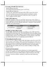
Powering ON/OFF KS-7410/7412 

Power ON KS-7410/7412 
Press down the power button to power on the POS.  

Power OFF KS-7410/7412 
In most cases, press the power button of the POS to power the system 
off. If the terminal fails to turn off the machine for unknown reasons, 
please be advised to hold the power button more than 10 seconds to 
force a shutdown of the system. 

Status LED Indicator 

LED status indicator, which is located at the bottom edge of the terminal, is 
mainly responsible for notifying users of the current system status by emitting 
various LED signals. In the chart provided below, it describes all the possible 
LED status as a quick reference. 

LED 

Status 

Description 

POWER LED 

Solid orange 

System standby 

Solid blue 

System ON 

Installing an Operating System 

You are highly advised not to install an operating system on KS-7410/7412 
without professional instructions. Not only might the careless handling during 
installation cause irreversible damage to your machine, but also the improper 
installation likely leads to system malfunction or failure. Please contact with 
your dealers about the issues of operating system installation. 

Performing System Recovery 

For KS-7410/7412 models with preloaded operating systems, Recovery DVD 
which includes useful utilities will be provided in the package to assist you in 
efficiently restoring or repairing your damaged system. However, you are not 
encouraged to recover your system without the help of system integrators. 
Please be advised to contact your service center for further assistance with 
system recovery.  

Operation Environment 

To prevent KS-7410/7412 from overheating, it is strongly suggested to 
position your terminal in a well-ventilated working environment. In doing so, 
please be advised to keep the POS terminal at least 25mm away from other 
devices to ensure the machine is properly cooled down and functioning 
normally. 

Summary of Contents for KS-7410

Page 1: ...ackage Contents 10 KS 7410 or 12 KS 7412 fanless touch terminal x 1 Power adapter x 1 Power cord x 1 User manual x 1 16930900030 Ver B0 http www posiflex com KS 7410 7412 Fanless Touch Terminal User Manual ...

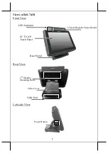
Page 2: ...2 Views of KS 7410 Front View Rear View Left side View Cable Exit 3 Track Magnetic Stripe Reader LED Indicator Cable Cover 2nd Display Mounting Holes 10 P CAP Touch Panel Power Button Base Stand ...

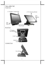
Page 3: ...3 Views of KS 7412 Front View Rear View Left side View Cable Exit 12 Resistive Touch Panel LED Indicator Cable Cover 2nd Display Mounting Holes Power Button Base Stand LED Indicator 12 P CAP Touch Panel ...

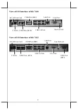
Page 4: ...w of I O Interface of KS 7412 DC In Power Jack CR Port LAN Port VGA Port COM Port DB9 COM Ports RJ50 USB 2 0 Ports Line Out Jack COM Ports RJ50 COM Port DB9 DC In Power Jack USB 2 0 Ports LAN Port VGA Port Line Out Jack COM Port DB9 CR Port ...

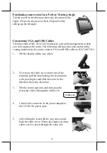
Page 5: ...structions for you to connect VGA and USB cables to KS 7410 7412 1 Tilt the display all the way down 2 To remove the cable cover at the rear of the terminal pull the four locking levers outwards with your fingers and slide the cover in the direction shown by the arrow 3 Tilt the screen upwards and then pass the necessary cables through the cable exit 4 Connect the connector of the power adapter to...

Page 6: ...own to prevent damage Installing Side Mount Upgrade Kits Located at left side on the back of the terminal side mount compartment is mainly used for installation of side mounted equipment including magnetic stripe reader RFID reader and fingerprint reader For detailed installation instructions please refer to the user manual specific to the device which you intend to mount KS 7410 KS 7412 Installin...

Page 7: ... without professional instructions Not only might the careless handling during installation cause irreversible damage to your machine but also the improper installation likely leads to system malfunction or failure Please contact with your dealers about the issues of operating system installation Performing System Recovery For KS 7410 7412 models with preloaded operating systems Recovery DVD which...

Page 8: ... x 2 RJ50 x 2 Parallel Port 1 port proprietary port connector inside service window Optional PS 2 Port Pin header inside service window Optional Standard USB Port USB 2 0 x 6 LAN Port 10 100 1000 Mb x 1 VGA Port VGA x 1 CR Port 1 controlling 2 CR via optional Y cable Audio Internal 2W speaker x 1 lineout jack Environmental Requirements Operating 0 C 40 C 20 RH 90 RH Storage 20 C 70 C 10 RH 90 RH A...

Reviews: