background image


Part 10 

WALL MOUNTING 

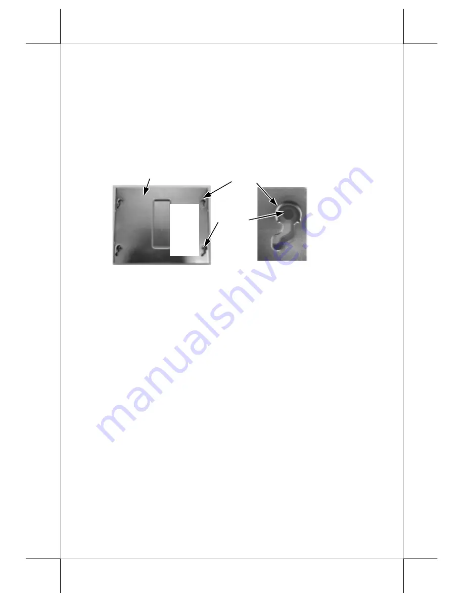
The major part in the wall mounting kit is a bracket as shown in the 

picture. Screw the bracket against the wall for mounting the Jiva TP/LT-
5700G / Jiva TP/LT-5800G in the direction that the wider parts of the 
matching holes are at the top as shown in the picture below. Align the four 
matching pegs on the back of the main unit with the four matching holes in the 
bracket to hold the main unit in the similar manner as installing the main unit 
onto the stand assembly. The stand assembly is not engaged in wall mount 
operation. 


LOCATION FOR INSTALLATION 

As the stand assembly is not involved in wall mount installation, the 

space required for wall mount application will take only the main unit into 
consideration. So the space required is 375 mm in width and 315 mm in height. 

For desk top/counter application, the adjustable stand assembly 

requires a base of 270 mm deep and 260 mm wide. However, please take also 
the main unit into consideration. If the main unit is tilted to near vertical 
position, the total height is 360 mm. When the main unit is tilted to near 
horizontal position, the total height required is 275 mm. 

OPERATING SYSTEM RECOVERY 

For Jiva TP/LT-5700G, if not using a remote boot operating system, 

the operating system exists in the Compact Flash Card. Therefore, once the 
Compact Flash is damaged for any reason, the thin client may fail to boot. 

bootable new Compact Flash Card will be required to have the 
workstation back to work

. Please follow instructions given by the System 

Integrator to deal with situations like that. One more advice for CF Card 
application is that in spite of the fact that it is used in the way like an ordinary 
HDD, usual system management utilities such as 

FDISK.EXE or 

FORMAT.COM shall never be used on CF Card

 otherwise the boot sector 

of operating system itself may be damaged and causing the CF Card no longer 
bootable. 

For Jiva TP/LT-5800G, the operating system exists in the HDD. Once 

Matching Holes 

Screw 
Holes 

Wall Mount Bracket 

Show 

this 

side 

out. 

Summary of Contents for Jiva LT-5700G

Page 1: ...mitation loss of data or profits resulting from the furnishing performance or use of this material This information is provided as is and Posiflex Inc expressly disclaims any warranties express implied or statutory including without limitation implied warranties of merchantability or fitness for particular purpose good title and against infringement The information in this manual contains only ess...

Page 2: ... 2 mouse port 3 4 serial ports with capability for 5V DC support reduce to 3 ports if RS232 interface touch panel is used 4 one parallel port 5 2 USB ports 6 one LAN port 10 100 base T Ethernet 7 one external VGA monitor port 8 one Compact Flash memory card connector for Jiva TP LT 5700G only 9 one DC 12 V power input connector 10 one UPS battery connector 11 one CR port for control over 2 cash dr...

Page 3: ...ader and finger print sensor Common security device upgrade SD100 covering option s from USB interface MSR or smart card reader and finger print sensor or iButton reader 2 in 1 security device upgrade SD200 covering options of USB interface MSR or optical scan type finger reader Bar code card reader BC 100U d Integrated rear top mount LCD customer display PD 302 e 2 in 1 cash drawer control cable ...

Page 4: ... release lever on the base backward to adjust the stand to the most horizontal position for ease of operation Insert the tip of the latchkey into a latch hole on one side near bottom of the main unit Turn this key counterclockwise to the end Do the same on the opposite side Be sure to take the key out of the hole before doing next operation Then push the lock release lever on the base backward to ...

Page 5: ...res A serial mouse is one example of a device that does not support handshaking Adjust the slack of each cable and close the cable cover Use the same plastic latchkey that is used when removing the cable cover but be sure to turn it in the clockwise direction to lock the cover in place Re adjust the tilt angle of the screen for best viewing SEPARATING MAIN UNIT In order to settle the touch termina...

Page 6: ...quirement for UPS battery in next chapter USING THE TOUCH POS CASH DRAWER The Jiva series is able to control the printer direct drive type Posiflex cash drawers Among them it is recommended that the Posiflex CR 4000 or CR 4210 be used since the terminal has been designed to compliment this cash drawer both mechanically and electrically The Jiva series will directly control the cash drawer using th...

Page 7: ...rrange all cables to come out of the area for mounting main unit from the bottom edge for ease of later operation PREPARING THE MAIN UNIT On the back of the main unit there are 4 matching pegs and a service window Push open the service window in the direction as indicated in the picture one can find a button cell battery socket two 1 x 2 JP6 9 and two 1 x 3 headers JP11 16 with 1 jumper each and t...

Page 8: ...f the Dongle and also 2 hooks on either top corner on rear side of main unit of the Jiva system Match the hooks to mount the Dongle to either corner of the Jiva system Should there be more than 2 Dongles to be installed in the application for the advantage of several fixed predetermined connections without need for connection alteration in process the third Dongle and afterwards have to attach to ...

Page 9: ...e lifting the main unit CONNECTING CABLES Connect the cables required to the appropriate connectors Please make sure that each connector has to be connected to the right port in the right orientation Some connectors have to be inserted till a click is heard such as the LAN connector It is recommended to screw on the connector once it is inserted such as the external VGA connector the LPT port conn...

Page 10: ... However please take also the main unit into consideration If the main unit is tilted to near vertical position the total height is 360 mm When the main unit is tilted to near horizontal position the total height required is 275 mm OPERATING SYSTEM RECOVERY For Jiva TP LT 5700G if not using a remote boot operating system the operating system exists in the Compact Flash Card Therefore once the Comp...

Page 11: ...http www posiflex com tw Now please follow instructions from your system integrator for software recovery Please refer to the System Protection section in chapter USING THE TOUCH POS for guidance on the Time Machine like system recovery OPERATING SYSTEM INSTALLATION This product is a highly professionalized equipment The installation of an OS into a machine without any preloaded OS could constitut...

Page 12: ...or 1 2 hours every month if the temperature exceeds 30 C When an UPS battery is installed in this equipment the environment should keep below 30 C to protect the life of the battery Temperature above 40 C must be strictly avoided as it could cause termination of battery life and unexpected result even if the battery is not in work The UPS battery can support basically the data preservation and smo...

Page 13: ... battery monitor disables the battery charging as designed while the UPS function of the system is originally enabled in other words the UPS battery is found out of order if actually installed there will be a popup message asking the user to agree disabling the UPS function The system will operate under deactivated UPS function no matter agreed or not However the monitoring goes on and the popup m...

Page 14: ...t some hardware registers may be confused causing trouble for system restart or even this forced power off please disconnect the UPS battery if installed and the AC power supply for few minutes This may allow all hardware registers to reset This switch can also be programmed as an ON only switch That means if the application program issues a command compliant with the Jiva series technical manual ...

Page 15: ...tup 2 Select Power Management Setup and enter PM Wake Up Events Go to item Ring Power Up Control and change the setting to Enabled then press F10 key to save and exit CMOS setup 3 Connect a RS232 MODEM to any of COM2 COM3 or COM4 and to a proper telephone line This system may then be powered off and will automatically boot up at the MODEM ringing By LAN Wakeup For LAN wakeup an operating caller sy...

Page 16: ...e is a function built in for system protection A screen as below will pop up for a short period of time in operation system booting up stage In normal application nothing has to be done and the system boot up continues However this system protection function is provided for our end users to fight against enormous virus attacks or malicious system invasions nowadays or even some possible system cra...

Page 17: ...y this action Pressing F2 key will have no response if your system integrator did not do the protection or if you have erased their effort by action in next paragraph Pressing the three key combination of Ctrl Alt F1 will restore your system right back to the pure OS status Please never take this action unless you know exactly what you are doing and what to do next The whole process may take quite...

Page 18: ...s exactly like a standard mouse However if the system is running under safe mode due to a previous improper shutdown or for any other reason most drivers are disabled in this mode and the touch panel calibration may not coincide with the mouse pointer It is recommended that a standard USB mouse or keyboard be used in this mode All the below mentioned mouse emulation functions can be manipulated th...

Page 19: ...e controller The Posiflex Touch Terminal Manager above should be disregarded In these models the COM4 position of the system will be covered in the connection area Removal of this cover will void the product warranty Once the RS232 touch controller driver is installed the user can utilize it to calibrate the touch screen define mouse button emulation modes enable right button emulation or define t...

Reviews: