7
6
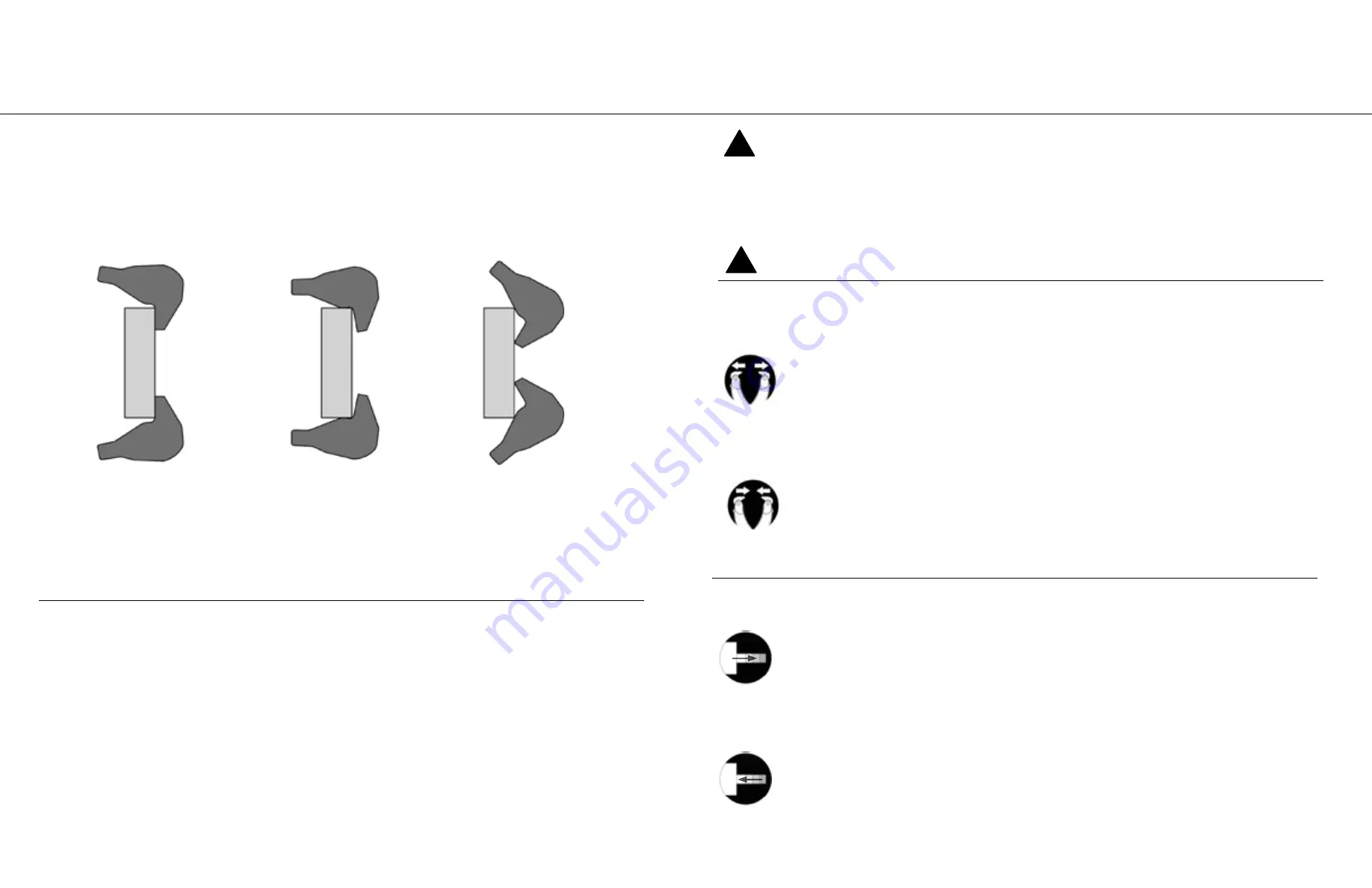
ADJUSTING JAW TIPS:
1. Adjust jaw tips by turning 1 ¼” cap screw.
NOTE:
Always use maximum pulling surface of jaw. To angle tip inward, turn cap screw clockwise. To angle tip outward, turn cap
screw counterclockwise. Before pulling, always make certain machined caps are properly fitted to curved surface.
Incorrect
Incorrect
Correct Alignment
POSI LOCK®
100-TON & 200-TON
Hydraulic Puller Systems
Adjustments (continued) | Removing puller from cart
ADJUSTING SLIDE ROLLERS:
1. Lower slide and puller assembly until it rests solidly on base.
2. Loosen 5/8” hex bolt.
3. Move roller using eye bolts on each side of roller.
4. Adjust roller until equal spacing is obtained between mast and slide tube on both roller side and opposite side.
5. Tighten locking nut on eye bolt.
6. Tighten 5/8” hex bolt.
100-TON:
REMOVING PULLER FROM THE CART:
1. Support puller weight using lifting brackets provided.
2. Close puller hoist vertical control valve.
3. Disconnect puller hoist hose coupler at control panel.
4. Remove 2 of the ½” bolts which fasten locking plate to the puller lift bracket.
5. Remove puller from cart by rotating cart while keeping puller stationary.
200-TON:
REMOVING PULLER FROM THE CART:
1. Support puller weight using lifting brackets provided.
2. Close puller hoist vertical control valve.
3. Disconnect puller hoist hose coupler at control panel.
4. On each slide, remove the top and bottom ½” bolts. Do this on both the left and right slide, removing a total of 4 bolts.
5. While keeping the puller supported and balanced, remove from the cart by moving the puller forward.
RETRACTING CYLINDER
:
I. Place cylinder control valve in the “Retract” position.
II. Activate pump with jog switch.
POSI LOCK®
100-TON & 200-TON
Hydraulic Puller Systems
Set-up | Pulling an object
SET-UP:
1. Transport the puller by use of the puller cart of forklift.
2. Line the puller up to the workpiece.
3. Open the jaws.
OPENING THE JAWS:
I. Place cylinder control valve lever in “Oil Supply” position.
II. Place cage control lever in “Jaw Open” position and activate pump by pushing remote switch to the “On”
position to open jaws to the desired spread.
CLOSING THE JAWS:
I. Place cylinder control valve lever in “Oil Supply” position.
II. Place cage control lever in “Jaw Closed” position and activate pump by pushing remote switch to the “On”
position to close jaws to the desired spread or for clamping.
EXTENDING CYLINDER
:
I. Place cylinder control valve in “Extend” position.
II. Activate pump with jog switch.
7. Adjust the jaw tips appropriately. See ADJUSTING JAW TIPS on page 4.
4. Position the workpiece to be removed in between the jaws.
5. Continue to adjust the height until the
workpiece and extending cylinder are aligned. See RAISING THE PULLER on page 3.
6. Close the jaws.
PULLING AN OBJECT:
1. Extend the cylinder ram towards the workpiece until there is contact.
2. Continue to extend the ram. The workpiece will begin to move gradually off the shaft.
3. Retract the cylinder.
4. Completely remove the workpiece.
NOTE:
On a single acting cylinder the cylinder ram will retract without activating the pump.
OPERATION IMPORTANT:
Hydraulic power is one of the safest methods for applying force when used correctly. Be sure to
read all instructions, warnings and cautions carefully.
Follow all safety precautions to avoid personal injury or property damage during system operation. Posi Lock cannot be responsible
for damage or injury resulting from unsafe use of product, lack of maintenance or incorrect product and/or system operation.
It is important that the operator has a full understanding of all the instructions, warnings, cautions and safety regulations before
starting to operate equipment. When in doubt contact Posi Lock at +1-701-797-2600.
MAINTENANCE:
Always clean the puller after use and store in a clean, dry place.
!
!


