


11
Notice
1.
Always ensure that the correct power voltage is used as a precaution against fire and electrical shock.
2.
Avoid exposing product to direct sunlight. Do not use product in areas of high humidity.
Doing so may cause low reliability and/or operational malfunction.
3.
Be careful of static electricity on PCB of system with anti-static appliances. Doing so may cause inferior
reliability and shorted product life.
4.
Keep product away from highly static areas. This may lead to inferior performance and reduced life cycle.
5.
Do not interfere with, or obstruct metal components inside product. Doing so may cause the risk of fire or
electric shock.
6.
Do not pull on power cable or peripheral devices’ connector cable. Doing so may cause fire, electric shock or
electronic system malfunction.
7.
Use caution when around other electronic devices with possible high frequency or electro-magnetic effects
e.g. Audio, Electronic-range etc. Doing so will lead to the serious risk of product malfunctioning or a system
error occurring.
8.
Ensure that batteries are replaced correctly. Failure to do this may result in sudden explosions.
9.
Dispose of used batteries properly according to the instructions.
Summary of Contents for BLUO D25
Page 1: ...Point of sale system BLUO D25 Use r manual BLUO_D25_UM_eng_PBUM_E Rev002 140926...
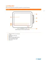
Page 5: ...5 Specification Outside size...
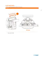
Page 15: ...15 Optional Devices 2nd LCD monitor 12 1 Optional Devices 2nd LCD monitor 10...
Page 20: ...20 Standard I O port...
Page 31: ...31 LCD monitor module Step4 Lift up the LCD monitor module and detach from the Stand...
Page 33: ...33 HDDModule Step4 See printed image for details Zoom in Check an arrow sign...
Page 46: ...46 CDP Option Step7 Reassemble a unit using the Reverse procedure of step 1 3 above...
Page 51: ...51 MSR Option Step3 Assemble the MSR Step4 I O part put holes in the sample place RJ45 PORT...
Page 68: ...68 LPT Option Step10 Reassemble a unit using the Reverse procedure of stpe1 5 above...
Page 72: ...72 USB PCB Option Step8 Use cutter and ripper to remove USB dummy ZOOM IN...
Page 77: ...77 RAM option Step8 Place Mother board as in image Stetp9 Install the Memory ZOOM IN...
Page 78: ...78 RAM option Step10 Assemble the SODIMM from the socket Retaining clip DDR SODIMM notch...
Page 79: ...79 RAM option Step11 Reassemble a unit using the Reverse procedure of stpe1 5 above...
Page 83: ...83 2nd storage HDD Option Step8 Assemble 4 screw from HDD bracket as show above ZOOM IN 1 2...
Page 94: ...94 Cash drawer Option Step8 Use cutter or ripper to remove Io bracket blanking ZOOM IN...
Page 95: ...95 Cash drawer Option Step9 Assemble a hexa bolt and fasten Screw to cash drawer ZOOM IN...
Page 104: ...104 6 OnboardTouch function Enable Disable selection USB_SEL 1 Disable Enable Default 1...
Page 111: ...111 2 4 Launch PXE 0Prom Disable Configuration options Disabled Enabled...
Page 118: ...118 2 10 Hardware Monitor Smart Fan Mode configuration Smart Fan Mode select...
Page 120: ...120 2 11 Chipset...
Page 122: ...122 2 13 Boot Display Configuration...
Page 124: ...124 Color depth 24Bits Select color Depth for LVDS...
Page 125: ...125 2 15 South Bridge parameters Into South Bridge Subdiredtory...
Page 127: ...127 2 16 Boot...