


107
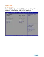
1.2 List Box
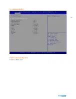
This box appears only in the opening screen. The box displays an initial list of configurable items in the menu you
selected.
1.3 Sub-menu
Note that a right pointer symbol (
▶
) appears to the left of certain fields. This pointer indicates that you can display a
sub-menu from this field. A sub-menu contains additional options for a field parameter. To display a sub-menu, move
the highlight to the field and press <Enter>. The sub-menu appears. Use the legend keys to enter values and move
from field to field within a sub-menu as you would within a menu. Use the <Esc> key to return to the main menu.
Take some time to familiarize yourself with the legend keys and their corresponding functions. Practice navigating
through the various menus and submenus. If you accidentally make unwanted changes to any of the fields, press <F6>
to load the fail-safe default values. While moving around through the Setup program, note that explanations appear in
the Item Specific Help window located to the right of each menu. This window displays the help text for the currently
highlighted field.
Summary of Contents for BLUO D25
Page 1: ...Point of sale system BLUO D25 Use r manual BLUO_D25_UM_eng_PBUM_E Rev002 140926...
Page 5: ...5 Specification Outside size...
Page 15: ...15 Optional Devices 2nd LCD monitor 12 1 Optional Devices 2nd LCD monitor 10...
Page 20: ...20 Standard I O port...
Page 31: ...31 LCD monitor module Step4 Lift up the LCD monitor module and detach from the Stand...
Page 33: ...33 HDDModule Step4 See printed image for details Zoom in Check an arrow sign...
Page 46: ...46 CDP Option Step7 Reassemble a unit using the Reverse procedure of step 1 3 above...
Page 51: ...51 MSR Option Step3 Assemble the MSR Step4 I O part put holes in the sample place RJ45 PORT...
Page 68: ...68 LPT Option Step10 Reassemble a unit using the Reverse procedure of stpe1 5 above...
Page 72: ...72 USB PCB Option Step8 Use cutter and ripper to remove USB dummy ZOOM IN...
Page 77: ...77 RAM option Step8 Place Mother board as in image Stetp9 Install the Memory ZOOM IN...
Page 78: ...78 RAM option Step10 Assemble the SODIMM from the socket Retaining clip DDR SODIMM notch...
Page 79: ...79 RAM option Step11 Reassemble a unit using the Reverse procedure of stpe1 5 above...
Page 83: ...83 2nd storage HDD Option Step8 Assemble 4 screw from HDD bracket as show above ZOOM IN 1 2...
Page 94: ...94 Cash drawer Option Step8 Use cutter or ripper to remove Io bracket blanking ZOOM IN...
Page 95: ...95 Cash drawer Option Step9 Assemble a hexa bolt and fasten Screw to cash drawer ZOOM IN...
Page 104: ...104 6 OnboardTouch function Enable Disable selection USB_SEL 1 Disable Enable Default 1...
Page 111: ...111 2 4 Launch PXE 0Prom Disable Configuration options Disabled Enabled...
Page 118: ...118 2 10 Hardware Monitor Smart Fan Mode configuration Smart Fan Mode select...
Page 120: ...120 2 11 Chipset...
Page 122: ...122 2 13 Boot Display Configuration...
Page 124: ...124 Color depth 24Bits Select color Depth for LVDS...
Page 125: ...125 2 15 South Bridge parameters Into South Bridge Subdiredtory...
Page 127: ...127 2 16 Boot...