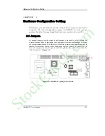


Hardware Configuration Setting
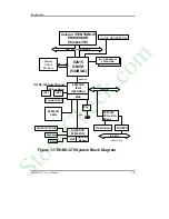
ROBO-679 User’s Manual
2-6
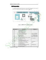
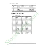
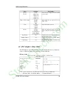
J6 : ATX Power Button Interface
PIN No.
Signal Description
1
Pull-high 100 ohm to +5V
2
Power Button Control Signal
J7/J8 : Serial Port-1/Port-2 Connector (2 x 5 shrouded header)
PIN No.
Signal Description
1
Data Carrier Detect (DCD)
2
Receive Data (RXD)
3
Transmit Data (TXD)
4
Data Terminal Ready (DTR)
5
Ground (GND)
6
Data Set Ready (DSR)
7
Request to Send (RTS)
8
Clear to Send (CTS)
9
Ring Indicator (RI)
10
N/C
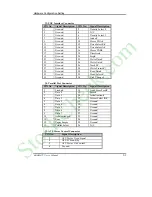
J9 : Standard IrDA Header
PIN No.
Signal Description
1
VCC (+5V)
2
IOVSB
3
IRRX
4
Ground
5
IRTX
6
OVCROFF (Over Current Off)
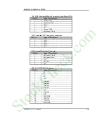
J10/J19 : Chassis/CPU Fan Power Connector
PIN No.
Signal Description
1
Ground
2
+12V
3
Pull-up 5V (For tachometer sense
signal)
J11 :
USB Interface Connector
[2x5 Pin Header]
PIN No.
Signal Description
PIN No.
Signal Description
1
+5V
2
N/C
3
SBD2- (USBP2-)
4
Ground
5
SBD2+ (USBP2+)
6
SBD3+ (USBP3+)
7
Ground
8
SBD3- (USBP3-)
9
N/C
10
+5V
StockCheck.com


