


NAR-7060 User’s Manual
13
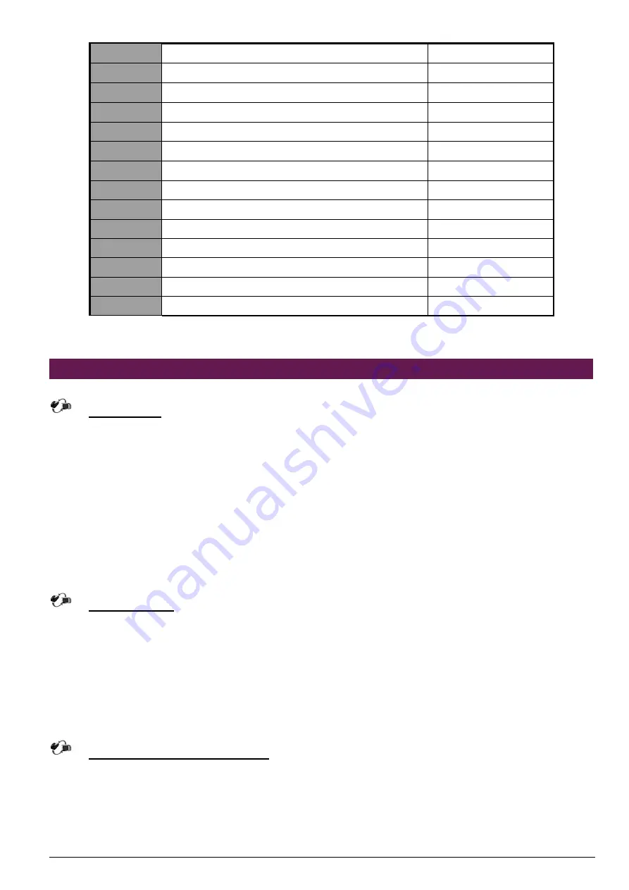
J13
Hook for MCH Heatsink
J14
Hook for MCH Heatsink
J15
PCI-X Slot
J16
Hook for MCH Heatsink
J17
Hook for MCH Heatsink
J18
ITP Port
J19
Connector for LED board
J21
COM2 Header 5X2 for LCD module
ATX1
ATX Power Connector
ATX2
12V Power Connector
CPUFAN1
CPU FAN Power Connector
CPUFAN2
CPU FAN Power Connector
SYSFAN1
SYSTEM FAN Power Connector
SYSFAN2
SYSTEM FAN Power Connector
2.12 Install a Different Processor
Install CPU
1.
Lift the handling lever of CPU socket outwards and upwards to the other end.
2.
Align the processor pins with holes on the socket. Make sure that the notched corner or dot
mark (pin 1) of the CPU corresponds to the socket's bevel end. Then press the CPU gently
until it fits into place. If this operation is not easy or smooth, don't do it forcibly. You need to
check and rebuild the CPU pin uniformly.
3.
Push down the lever to lock processor chip into the socket.
4.
Follow the installation guide of cooling fan or heat sink to mount it on CPU surface and lock it
on the socket 603.
5.
Be sure to follow particular CPU speed and voltage type to adjust the jumper settings properly
for all boards.
Remove CPU
1.
Unlock the cooling fan first.
2.
Lift the lever of CPU socket outwards and upwards to the other end.
3.
Carefully lift up the existing CPU to remove it from the socket.
4.
Follow the steps of CPU installation to change to another one or place handling bar to close
the opened socket.
Configure Processor Speed
Please into BIOS menu select Frequency/Voltage Control
,
change CPU Clock Ratio
to20X