background image

11 -  ENG

ELECTRICAL POWER REQUIREMENTS

I       

WARNING

Risk of electrical shock. Improper electrical grounding 

can result in electrical shock. The wiring should be done by a qualified 

electrician.

ELECTRICAL WIRING

Refer to the air compressor’s serial label for the unit’s voltage and amperage 

requirements. Ensure that all wiring is done by a licensed electrician, in 

accordance with the National Electrical Code..

MAIN POWER PANEL


For best performance and reliable starting, the air compressor must be installed 

on a dedicated circuit, as close as possible to the electrical power panel. 

Provide circuit breaker or fuse protection at your main power panel. Use time 

delay fuses on the circuit, because the compressor will momentarily draw 

several times its specified amperage when first started. 

NOTE:

  A circuit breaker is recommended. If the air compressor is connected to 

a circuit protected by a fuse, use dual element time delay fuses (Buss Fusetron 

type “T” only).

MAIN POWER DISCONNECT SWITCH

Install a main power disconnect switch in the line from the panel to the 

compressor. The main power disconnect switch must be located near the 

compressor, for ease of use and safety. When turned OFF, the main power 

disconnect switch shuts off all power to the compressor. When it is turned ON, 

the compressor will start and stop automatically, controlled by the pressure 

switch.

LOW VOLTAGE PROBLEMS

Low voltage will cause difficult starting or an overload. Low voltage can be 

caused by a low supply voltage from the local power company, other equipment 

running on the same line, or inadequate wiring. If any other electrical devices are 

drawing from the compressor’s circuit, it may fail to start.

Low voltage to the compressor can be caused by a supply wire of insufficient 

gauge for the distance between the compressor and the power source. The 

longer the distance, the larger the wire gauge (lower the number) must be, to 

overcome the inherent voltage loss caused by the wire resistance. Refer to the 

National Electrical Code to determine proper wire size for your circuit.

If the wiring is not adequate, the input voltage will drop by 20 to 40 volts at 

startup. Low voltage or an overloaded circuit can result in sluggish starting that 

causes the circuit breaker to trip, especially in cold conditions.

GROUNDING INSTRUCTIONS

This product must be connected to a grounded, metallic, permanent wiring 

system, or an equipment - grounding terminal or lead on the product.

Summary of Contents for PXCMLC3706056

Page 1: ...o por correa Single Stage Belt Drive Electric Air Compressors Compresseurs d air électriques à un étage à entraînement par courroie Français Page 31 Español Página 60 Instruction manual Manuel d instructions Manual de instrucciones PXCMLC3706056 200 2887_Rev A_7 12 ...

Page 2: ...LAGE DU MOTEUR 40 MODE D EMPLOI 40 44 Rodage de la pompe 40 Mise en marche quotidienne 42 Arrêt 42 ENTRETIEN 43 46 Vidange du réservoir 43 Vérification du niveau d huile 43 Vidange d huile 43 Tension de la courroie 44 Alignement de la poulie 45 Nettoyage du filtre à air 46 Vérification de soupape de décharge 46 Essai d étanchéité 46 Entreposage 46 ENTRETIEN PÉRIODIQUE 46 DÉPANNAGE 47 48 DESSIN DES...

Page 3: ...Pour vous aider à identifier la nature de ces informations nous utilisons les symboles suivants Veuillez lire le manuel et prêter attention à ces sections DANGER POTENTIEL POUVANT ENTRAÎNER DE GRAVES BLESSURES OU LA MORT DANGER POUVANT CAUSER DES BLESSURES GRAVES VOIRE MORTELLES DANGER POUVANT CAUSER DES BLESSURES MOYENNEMENT GRAVES OU L ENDOMMAGEMENT DE L APPAREIL I DANGER I AVERTISSEMENT I ATTEN...

Page 4: ...rns or other injuries DO NOT touch the pump manifold or transfer tube while the pump is running Allow them to cool before handling or servicing Keep children away from the compressor at all times 7 RISK TO BREATHING Be certain to read all labels when you are spraying paints or toxic materials and follow the safety instructions Use a respirator mask if there is a chance of inhaling anything you are...

Page 5: ...ors some of which include operating conditions ambient conditions proper installations field modifications and the level of maintenance The exact effect of these factors on air receiver life is difficult to predict If proper maintenance procedures are not followed internal corrosion to the inner wall of the air receiver tank can cause the air tank to unexpectedly rupture allowing pressurized air t...

Page 6: ...See pages 8 9 for typical installation of the 60 gallon model 4 To prevent damage to tank and compressor on stationary models the tank must be shimmed so the pump base is level within 1 8 to distribute oil properly All feet must be supported shimming where necessary prior to attaching to the floor Fasten all feet to floor We also recommend the use of vibration pads 094 0137 under tank feet 5 Faste...

Page 7: ...uction in a clean well ventilated area to ensure sufficient air flow and cooling c In cold climates locate the compressors in a heated building when not in use This will reduce problems with lubrication motor starting and freezing of water condensation d Remove the compressor from the shipping pallet and place it on the floor or a hard level surface The compressor must be level to ensure proper lu...

Page 8: ...rcooler J Line filter K Drip tee with drain L Air water filter with petcock M Regulator N Lubricator P Quick coupler R Air hose to tool T Flexible air line U Lubricated supply line I WARNING I CAUTION Risk of bursting resulting in injury Never use Plastic pipe for compressed air Risk of property damage Never use lubricator for paint spraying or similar applications ...

Page 9: ...uld also be installed in the positions shown AIR PRESSURE REGULATION Install an air regulator in the drop line for each tool to regulate air pressure to that tool Never exceed the maximum pressure rating of the tool AIR LUBRICATION Install an air lubricator only for those tools requiring lubrication Do not use a lubricator for paint spraying or similar applications The oil will contaminate the pai...

Page 10: ...ore unplugging the compressor Pressure Relief Valve see B If the pressure switch does not shut down the motor when pressure reaches the preset level this valve will pop open automatically to prevent over pressurization To operate manually pull the ring on the valve to relieve air pressure in the tank Tank Pressure Gauge see C This gauge measures the pressure level of the air stored in the tank It ...

Page 11: ...ear the compressor for ease of use and safety When turned OFF the main power disconnect switch shuts off all power to the compressor When it is turned ON the compressor will start and stop automatically controlled by the pressure switch LOW VOLTAGE PROBLEMS Low voltage will cause difficult starting or an overload Low voltage can be caused by a low supply voltage from the local power company other ...

Page 12: ...king the Oil in the maintenance section 3 Open the petcock see F Escaping air and moisture can propel debris that may cause eye injury Wear safety goggles when opening petcock 4 Turn ON the main power disconnect switch Turn the pressure switch to the AUTO position see D The motor should start Allow the compressor to run for 30 minutes to break in the internal parts NOTE After about 30 minutes if t...

Page 13: ...13 ENG OPEN CLOSE F E Fig 6 ...

Page 14: ...g the tank High temperatures are generated by the pump To prevent burns or other injuries DO NOT touch the pump or transfer tube while the pump is running Allow it to cool before handling or servicing Keep children away from the compressor at all times NOTE If the unit does not operate properly SHUT DOWN IMMEDIATELY and contact a qualified service center SHUTDOWN Fig 6 1 Turn the pressure switch t...

Page 15: ...day I WARNING Be sure to wear protective eyewear Relieve the air pressure in the system and open the petcock on the bottom of the tank to drain CHECKING THE OIL Check the level of oil in the pump with the sight glass The pump oil level must be between A and B See Fig 7 Do not overfill or underfill NOTE Use synthetic blend non detergent air compressor oil CHANGING THE OIL Remove the oil plug C Fig ...

Page 16: ...and belt life The correct tension exists if a deflection see A of 1 2 13 mm occurs by placing 5 lb 2 3 kg of force see B midway between the motor pulley and the pump flywheel See Fig 8 This deflection can be adjusted by the following procedure The pulley should be carefully aligned with the flywheel and all setscrews should be kept tight 1 Remove the belt guard 2 Loosen the motor mounting bolts 3 ...
Page 17: ...istances should be the same as at point C If D or E are different from C there is a misalignment which must be corrected before the compressor is run To correct a pulley misalignment use the following procedure 1 Remove the belt guard 2 Loosen the motor mounting bolts 3 Loosen the setscrew on the motor pulley 4 Align the motor pulley with the pump flywheel C D E 5 Retighten the motor pulley setscr...

Page 18: ...e of your air compressor If you suspect a leak spray a small amount of soapy water around the area of the suspected leak with a spray bottle If bubbles appear repair or replace the faulty component Do not overtighten any connections STORAGE Before storing the compressor for a prolonged period use an air blow gun to clean all dust and debris from the compressor Disconnect the power cord and coil it...

Page 19: ...ubes or check valve as required Compressor stalls Low voltage motor Furnish adequate power Bad check valve Replace the check valve Seized pump Contact authorized service center Low discharge pressure Air leaks Tighten or replace leaking fittings or connections Do not overtighten Leaking valves Contact authorized service center Restricted air intake Clean or replace air filter element s Blown gaske...

Page 20: ...ooling surfaces Clean all cooling surfaces thoroughly Restricted air passages Replace transfer tubes and or unloader Excessive belt wear Pulley out of alignment Realign pulley with compressor flywheel Improper belt tension Readjust Pulley wobbles Replace the pulley and check for a damaged crankshaft or flywheel Compressor won t start in cold temperatures Too much back pressure in tank Open petcock...

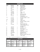
Page 21: ...om connect 2 034 0226 1 Switch pressure includes items 3 4 7 3 071 0033 1 Strain relief 4 061 0216 1 Screw 5 136 0005 1 Valve ASME 6 N A 1 Plug 1 4 7 136 0090 1 Valve bleeder N A These are standard parts available at your local hardware store Torque to 17 24 lb in Torque to 125 150 lb in Notes ...

Page 22: ...22 ENG PARTS DRAWING Note Torque to 85 90 lb in Note Tighten compression nut handtight plus 1 full turn ...

Page 23: ...replacement parts see pages 24 25 16 068 0092 1 Connector 17 058 0007 2 Nut 3 8 O D tube 18 145 0313 1 Tube transfer 19 145 0082 1 Tube bleeder 1 4 x 28 20 068 0002 1 Connector 21 031 0066 1 Check Valve 1 2 x 3 8 22 See page 21 1 Manifold assembly 23 N A 1 Nipple 1 4 x 2 1 2 24 160 0342 1 Motor See capacitor table below 25 098 2856 1 Label warning N A These are standard parts available at your loc...

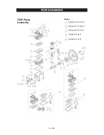
Page 24: ...24 ENG PARTS DRAWING 755H Pump Assembly Torque to 25 27 lb ft Torque to 14 16 lb ft Torque to 9 12 lb ft Torque to 8 lb ft Torque to 5 lb ft Notes ...

Page 25: ... A 1 Oil drain plug 3 8 NPT 24 032 0072 1 Oil sight glass w o ring 25 053 0100 1 Crankshaft 26 051 0100 1 Bearing 206 27 046 0284 1 Gasket 28 077 0172 1 Carrier 29 046 0285 1 Oil seal 30 044 0064 1 Flywheel 12 A groove 31 146 0026 1 Key 5MM x 5 MM 32 N A 1 Flywheel washer 33 N A 1 Screw M8 x 25 34 051 0098 2 pr Insert bearing 35 047 0086 2 Rod 36 048 0116 2 Piston assembly 37 054 0235 2 Ring Set I...

Page 26: ...ot apply to you What the Company Will Do the company will cover parts and labor to rem edy substantial defects due to materials and workmanship during the first year of ownership with the exceptions noted below Parts used in repair of whole goods or accessories are warranted for the balance of the original warranty period What is not covered Under This Warranty Failures by the original retail purc...

Page 27: ...delines Operation below proper oil level or operation without oil Gas Engines if product is equipped with a gas engine see engine manual for specific engine manufacturer s warranty coverage Parts purchased separately The warranty for parts purchased separately such as pumps motors etc are as follows From Date of Purchase All single two stage pumps 1 year Electric motors 90 days Universal motor pum...

Page 28: ... CONSEQUENTIAL AND INCIDENTAL DAMAGES UNDER ANY AND ALL WARRANTIES OTHER CONTRACTS NEGLEGENCE OR OTHER TORTS IS EXCLUDED TO THE EXTENT EXCLUSION IS PERMITTED BY LAW FREE WARNING LABEL REPLACEMENT If your warning labels become illeg ible or are missing call 1 888 895 4549 for a free replacement ...

Page 29: ...xchange for dangerous exhaust or vapors Dedicated circuit An electrical circuit reserved for the exclusive use of the air compressor ASME American Society of Mechanical Engineers Indicates that the components are manufactured tested and inspected to the specifications set by ASME CSA Canadian Standards Association Indicates that the products that have this marking have been manufactured tested and...

Page 30: ... transactions and a copy of your sales receipt may be requested Record the model number serial number and date purchased in the spaces provided below Retain your sales receipt and this manual for future reference When needing service please contact the nearest authorized Service Center or call PRODUCT SERVICE In U S A or Canada Toll Free 1 888 895 4549 Fax 1 507 723 5013 Model No Serial No Date Pu...

Reviews: