background image

!

OPEN UV PORT 

ON FILTER COVER

. Disconnect Power Before Replacing 

Lamp. Never stare at or expose skin to UV light. It can damage eyesight and burn skin. 

Risk of Electric Shock. Disconnect power before servicing. Connect 

only to a circuit that is protected by a ground-fault circuit-interrupter (GFCI). Do not immerse ballast 

in water. For household use only.

1)  Effective useful bulb life is one season. The bulb will continue to illuminate long after the UV radiance has 

diminished. For best results replace bulb annually.

2)  Periodically clean the quartz sleeve.   Always allow unit to cool before disassembly. Carefully disassemble and 

clean outside using a solution of 30% white vinegar to water. Allow to soak to soften scale or build-up.  Use a 

bottle brush and mild detergent to clean inside of quartz sleeve. Make certain inside of tube is dry before 

reassembly. Lubricate O-Rings with 


 before reassembling. 


Note that if Quartz sleeve or UV lamp shows any signs of cracks or fissures it cannot be used and must be replaced.  


:

• Never stare at or expose skin to UV light. It can damage eyesight and burn skin. 

• UV Clarifier will not light when removed from the quartz sleeve.  The built-in safety switch disables power when 

not assembled. 

• Do not defeat the safety features by bypassing the built in safety switch.

• If a second UV port is available a second UV unit can be installed. Check model compatibility.

• Save the plain UV port cap. It is needed to close off UV port when UV Clarifier is removed. For example, during 

winterization.

• Ballast is enclosed in a double insulated case. Never cut power cord. Do not modify the plug provided with the 

appliance; if it will not fit the outlet, have a proper outlet installed by a qualified electrician.

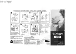
UV CLARIFIER INSTALLATION AND 

OPERATING INSTRUCTIONS: 

If your pressure filter was supplied with a UV clarifier, the lamp 

must be installed.

1) Unscrew the threaded ring and remove the UV clarifier / ballast 

assembly that is pre-installed into the cover of the filter. 

2) Remove the quartz sleeve by firmly holding the black collar 

section and turning it counter-clockwise until it disengages from 

the lamp socket assembly. 

3) Unpack the lamp and insert the contact pins on the lamp base 

completely into the lamp socket. 

  • For the 9 Watt unit:  Continue to step 4.

  • For the 18 & 36 Watt unit: Find the lamp retainer in the lamp 

box and slide it onto the lamp until it is snug in the socket. 

Next   insert the alignment disk onto the end of the lamp to 

center it in the quartz sleeve. 

4) Make certain that the flat gasket and O-rings are properly 

installed. See FIGURE 1. Flat gasket sits on top of the of the quartz 

sleeve and O-ring fits outside the tube, under the top flange. 

5)  Use Silicone grease to Lubricate Gasket & O-ring for easier 

assembly. Never use petroleum based lubricants. 

6)  Insert the UV lamp assembly into the Quartz sleeve and hand 

tighten - turning clockwise until secure.

7)  Insert the lamp / quartz sleeve assembly into either of the UV 

port openings in the pressure filter cover. 

8)  Rotate the threaded ring of the UV fixture clockwise onto the 

filter cover’s threads until tight.

9) After COMPLETE installation, UV Clarifier can be briefly tested; plug the 

power cord into an appropriately rated grounded GFCI protected outlet to 

check.  The UV light can be safely viewed through the clear plastic cap on the 

fixture. After testing, disconnect power until the filter is running. The UV unit 

should only be powered on when filter is fully assembled with water circulating.

MERCURY WARNING: LAMP CONTAINS MERCURY, 

MANAGE IN ACCORDANCE WITH DISPOSAL LAWS. 

WWW.LAMPRECYCLE.ORG

NOTE: YOUR FILTER AND UV 

ACCESSORIES 

MAY VARY FROM 

REFERENCE ILLUSTRATION.

FIGURE 1

QUARTZ 

SLEEVE

O-RING 

UNDER TOP 

FLANGE

FLAT GASKET

ALIGNMENT 

DISK

LAMP 

RETAINER





EXTRA UV 

PORT CAP 

(removed)

LAMP SOCKET 

WITH SAFETY 

SWITCH

UV LAMP

THREADED 

RING

UV FIXTURE 

WITH BALLAST

POSITION 

O-RING 

OUTSIDE THE 

TUBE, BELOW 

THE FLANGE

FLAT GASKET 

SEATS ON TOP 

OF QUARTZ 

SLEEVE

NOTE POSITION OF FLAT 

GASKET AND O-RING. 

Summary of Contents for Clearguard 16000

Page 1: ... CARE AND OPERATING INSTRUCTIONS ZG400 rev J 04 22 MODELS ITEM No UV With UV 120V 230V 2700 05610 05615 05617 5500 05620 05625 05627 8000 05630 05635 05637 16000 05640 05645 ...

Page 2: ...nies to grow The time required varies depending on climate weather condi tions fish load and feed rates Until the colonies grow large enough the pond owner must take care to monitor levels of ammonia and nitrates in the water and take appropriate measures to correct any dangerously high levels CAUTION Note that smaller filter media cannot be used with this filter It will pass into valve possibly c...

Page 3: ... à utiliser pour le luminaire portable pour site humide Les prises sont disponibles avec une protection GFCI intégrée et peuvent être utilisées pour cette mesure de sécurité 2 Utilisez uniquement avec une rallonge pour utilisation à l extérieur telle qu une rallonge de type SEW SEOW SEOOW SOW SOW STOW STOW STOW STOOW SJEW SJEOOW SJW SJOW SJOOW SJTOW SJTOW ou SJTOOW 3 Cet ensemble portable de lumin...

Page 4: ...eparate parts keeping all O rings protrudes from the bottom of the cover Cautiously place the cover to avoid damaging the quartz sleeve The UV lamp is packed in the upper protective packaging in a small separate box Handle it carefully it will be installed after the port cap This must be kept to cover UV port when winterizing Check that the drum divider is properly aligned in the filter drum track...

Page 5: ...O SLIP ADAPTER OR BARB FITTING Filter US Metric US SLIP ADAPTER US ONLY If your pressure filter was supplied with a UV clarifier the lamp is packed separately and must be installed Refer to instructions on page 8 of this manual for installation and operation Once cover is pressed down evenly place the clamp around the drum and cover flanges and pull the open end closed Note that it is best to posi...

Page 6: ...Check that pressure gauge pointer is in the Green zone Run filter with Foam Filter pad and Biomatrix Ball media at first The Biomatrix Ball media works best when the filter s bacteria colonies are established It takes a few weeks for the bacterial colonies to grow on the media and be effective for filtration During the waiting period for biological filtration the filter pad will collect debris and...

Page 7: ... washing TOP VALVE SET TO 4 BACKWASH time the pump is turned on The pointer should be in the green zone to ensure that the installa tion is correct The Gauge should not solely be relied upon to indicate the need for a backwash Always monitor backwashing is necessary the pump and check for the cause of the when the pointer is in the red zone GREEN ZONE YELLOW ZONE RED ZONE 2 Disconnect hoses that a...

Page 8: ...nd remove the UV clarifier ballast assembly that is pre installed into the cover of the filter 2 Remove the quartz sleeve by firmly holding the black collar section and turning it counter clockwise until it disengages from the lamp socket assembly 3 Unpack the lamp and insert the contact pins on the lamp base completely into the lamp socket For the 9 Watt unit Continue to step 4 For the 18 36 Watt...

Page 9: ...sition 5 CLOSED This position prevents any water in the pond from siphoning into the drum during the draining process 3 Remove the drain plug at the bottom of the filter to empty the drum You can purchase Item No 15675 ClearGuard Backwash Kit w o Air Pump which includes a Drain Plug Adapter NPT barbed fitting ShutoffValve andVinylTubing This kit will allow the water being drained from the drum to ...

Page 10: ... through valve not filter If still slow make adjustments to set up Outlet is clogged Check for obstructions and clear up outlet Filter drum is leaking at perimeter O Ring or Gasket is missing twisted dirty or was not lubricated Turn off pump Open filter and remove clean re seat and lubricate O Ring g asket Attach cover checking alignment of tab slot and thoroughly tighten clamp knob Water pressure...

Page 11: ...z Sleeve 11 2 INLET FITTINGS Includes parts 1 2 3 4 O rings 1 2 WASTE OUTLET FITTINGS Includes parts 2 INLET FITTINGS Includes parts 7 8 9 10 O Rings 7 8 9 11 O Rings 2 WASTE OUTLET FITTINGS Includes parts 3 INLET WASTE OUTLET FITTINGS Includes parts 13 14 15 SMALL FILTER PAD FOR 2700 5500 8000 MODELS Part 26 151 4 DIA LARGE FILTER PAD FOR 16000 MODEL Part 26 20 DIA LAMP ONLY 120V 9 WATT Part 35 L...

Page 12: ...do not constitute warranties and shall not be relied upon by the user and are not part of this contract Neither the seller nor the manufacturer shall be liable for any injury loss or damages direct incidental or consequential including but not limited to incidental or consequential damage for lost profits lost sales injury and inability to use the product and the user agrees that no other remedy i...

Reviews: