Workbook 4
Controller SIGMATEK - Boiler control
7
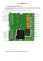
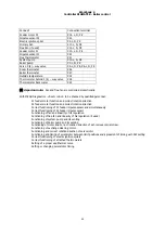
2.1.1.1 Technical base data
HZS521-G
Supply voltage
230 V AC +/- 10 %
(Input voltage for the power transformer on the power board, input
voltage for the STB, phase for the phase angle, relays and Triac outputs)
Power supply fre-
quency
45 - 65 Hz
Total current consumption 200 mA + current consumption of the
connected loads (max. 16 A)
Power supply transformer
Supply for the power board and CPU electronics
Supply for Heater Lambda sensor: 200 mA
Current
consumption of
supply (230 V AC)
The power supply is switched of STB, L-STB
Loads connected over fuse F4 (3,15 AT):
X11 primary fan: maximum
690 W/ maximum 3 A
Loads connected over fuse F5 (10 AT):
X14
Screw: maximum 690W/ maximum 3 A
Loads connected over fuse F6 (10 AT):
X9 Turbine: maximum 2300 W/
maximum 10 A
Loads connected over fuse F7 (10 AT):
X8 Ignition: maximum 2300 W/
maximum 10 A
Loads connected over fuse F8 (10 AT):
X5 heat exchange cleaner: maximum 690 W/
maximum 3 A
X6 grate open: maximum 690 W/
maximum 3 A
X7 grate closed: maximum 690 W/
maximum 3 A
The power supply not switched over STB, L
Loads connected over fuse
F9 (10 AT):
X10 boiler circuit return flow pump: maximum 2300 W/
maximum 10 A
HZS532-1
Internal
electronics power
supply
+24 V (from HZS 511), must be connected to the expansion
controller
Relay power
supply
230 VAC
Fuse
10 A for relay outputs
+24 V current
consumption
HZS 532-1: maximum 60 mA (without relays) Maximum
120 mA (with relays) HZS 532-1 with 5 expansion modules,
maximum 350 mA
HZS533, HZS535
Internal
electronics power
supply
+24 V (from HZS 511), must be connected to the expansion
controller
Relay power
supply
230 VAC
Fuse
5 A for relay outputs and/or 3 A for solar module
+24V current
consumption
HZS 533 maximum 15 mA (without relays) Maximum 40
mA (with relays)
Summary of Contents for Sigmatek
Page 1: ......
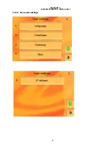
Page 16: ...Workbook 4 Controller SIGMATEK Boiler control 15 3 3 1 2 Menu users settings ...
Page 21: ...Workbook 4 Controller SIGMATEK Boiler control 20 Actual values Configuration ...
Page 28: ...Workbook 4 Controller SIGMATEK Boiler control 27 Load from USB Save on USB ...
Page 33: ...Workbook 4 Controller SIGMATEK Boiler control 32 ...
Page 35: ...Workbook 4 Controller SIGMATEK Boiler control 34 ...
Page 36: ...Workbook 4 Controller SIGMATEK Boiler control 35 i ...
Page 38: ...37 Picture No 7 Circuit diagram control unit ...
Page 39: ...38 Picture No 8 Circuit diagram module HZS 533 ...
Page 40: ...39 Picture No 9 Circuit diagram HZS 533 HZS 53 ...

