background image

Workbook 4  

Controller SIGMATEK - Boiler control 

 36 


4  GUARANTEE AND LIABILITY FOR DEFECTS 

The manufacturer provides guarantee: 
- for the boiler on a period of 24 months from the date of putting into operation, however, no longer than 
30 months from the date of shipment from the manufacturing plant 
- for the boiler body on a period of 60 months from the date of putting into operation 
- ceramic parts are not covered by the warranty. Its durability is dependent on the way of operation of boiler and their 
guaranteed durability is 12 months. 
 

GUARANTEE CONDITIONS 

1) User is obliged to ensure installation of the boiler and putting it into operation only by an 
authorized servicing organization which has the manufacturer's accreditation and the user is also 

obliged to send the 

letter of guarantee number 1 

to the manufacturer's address immediately 

after the product has been put into operation. 


2) The boiler has to be operated only within these Instructions for operation and only prescribed fuel 
may be used (wood pellets - 

φ

6-8.5 mm), free from any admixtures and foreign object. Alternative fuel must be approved 

by the boiler manufacturer. 
 

3) If the user wants to claim any form of guarantee, he/she has to submit duly filled in 

letter of 

guarantee number 2


4) The user is obliged to demonstrate that the product was maintained in regular intervals which are 
described in the chapter "MAINTENANCE". Regular annual maintenance has to be done by trained person who is also 
responsible for the record of it within 14 days (list is part of manual) / service intervention  or repaired has to be correctly 
recorded and sanded to a manufacturer.  
 
5) Every notification of defect has to be done in writing to the address of the manufacturer 
immediately after having been ascertained. 


The manufacturer reserves the right of product innovations, which may not be part of this manual. 


Important:  

Recommended hydraulic connections are principled diagrams created by manufacturer on the basis of 
practical experience in the operation of boilers KP. 

The user can use the application unchanged as well as in particular modification to the best solution of 
heating system. 

This is primary responsibility of the designer and implementer of the heating system -


which is why the 

Ponast company cannot take over the guarantee for the functionality of a particular solution of heating 
system. 


5  DISPOSAL OF PRODUCT AFTER TEH END OF ITS SERVICE LIFE 

Disposing of the Product is done in accordance with the generally applicable regulations. 

 
The following main kinds of waste will be generated after the end of the product´s service life: 
Control unit with sensing and control elements  

–  waste code 200136, category O. 


Summary of Contents for Sigmatek

Page 1: ......

Page 2: ...om a chimney of a building from a furnace or from any fixed boiler if located in a designated smoke control area It is also an offence to acquire an unauthorised fuel for use within a smoke control area unless it is used in an exempt appliance exempted from the controls which generally apply in the smoke control area The Secretary of State for Environment Food and Rural Affairs has powers under th...

Page 3: ...2 Menu users settings 15 3 3 1 3 Menu Service 18 3 3 2 Menu heating circuits 28 3 3 2 1 Tank 29 3 3 2 2 Sanitary water 31 3 3 2 3 Heating circuit 33 4 GUARANTEE AND LIABILITY FOR DEFECTS 36 5 DISPOSAL OF PRODUCT AFTER TEH END OF ITS SERVICE LIFE 36 PICTURES Picture No 1 Control unit configuration 4 Picture No 2 HZS 521 G Connector and terminal electronics layout 5 Picture No 3 Module HZS 532 1 6 P...

Page 4: ...dvantages of products CONTROL UNIT with modern design controls operation of the boiler ensures automatic operation high operational reliability long distance control Colour TFT display 5 7 with touch screen Remote control over TCP IP USB User friendly controlling Operation modes Equitherm Modulation or Fixed power Two heating circuits and sanitary water in basic configuration Possibility to contro...

Page 5: ...tional configuration Picture No 1 Control unit configuration Configuration Name Type Options Order code Control unit boiler function module HZS 521 G Standard Terminal touchscreen HZS 555 S Standard Module extension HZS 532 1 Standard Module heating circuit accumulation tank HZS533 Optional Module solar HZS535 Optional Type and number of circuit Type and number of module HC1 SWT HZS 521 G HZS532 1...

Page 6: ... system All interfaces and connections for controlling of the boiler are located on the control board Picture No 2 HZS 521 G Connector and terminal electronics layout Ambient temperature sensor HC1 mix temp Backwater temp Sanitary water temp Exhaust temp Sanitary water top Sanitary water bottom Room thermostat 3 Room thermostat 2 SWT thermostat Room thermostat 1 Impulse sensor 2 Impulse sensor 1 R...

Page 7: ...Workbook 4 Controller SIGMATEK Boiler control 6 The control unit always contains modules HZS 521 G and HZS 532 1 Picture No 3 Module HZS 532 1 HZS533 HZS533 HZS535 Picture No 4 Other modules ...

Page 8: ...um 10 A Loads connected over fuse F7 10 AT X8 Ignition maximum 2300 W maximum 10 A Loads connected over fuse F8 10 AT X5 heat exchange cleaner maximum 690 W maximum 3 A X6 grate open maximum 690 W maximum 3 A X7 grate closed maximum 690 W maximum 3 A The power supply not switched over STB L Loads connected over fuse F9 10 AT X10 boiler circuit return flow pump maximum 2300 W maximum 10 A HZS532 1 ...

Page 9: ...uch screen can only be cleaned with a soft damp cloth To dampen the cloth a screen cleaning solution such as antistatic foam water with detergent or alcohol should be used First spray the cleaning fluid on the cloth and not directly on the terminal The cleaning solution should not be allowed to reach the terminal electronics for example through the ventilation slots No erosive cleaning solutions c...

Page 10: ...nd lighting LED Contrast 600 Brightness Typically 350 cd m Angle CR 10 Left right below 75 above 60 Environmental conditions Storage temperature 10 85 C Operating temperature 0 50 C Humidity 10 90 uncondensed EMV stability EN 61000 6 2 noise immunity EN 61000 6 4 noise emission Vibration tolerance EN 600068 2 6 2 9 Hz Amplitude 3 5 mm 9 200 Hz 1 g 10 m s Shock resistance EN 60068 2 27 15 g 150 m s...

Page 11: ...personnel only Connect the particular appliances according with connection diagram During connecting the equipment must be shut down with the main switch or disconnected from power supply by pulling the electric cord from the outlet 1 Relay for electric ignition 2 Burner thermostat 3 Cover control unit 4 2x M4 5 Boiler thermostat 6 Control unit ...

Page 12: ...tion and correct rotation direction F2 feeder motor function and correct rotation direction Correct functioning of F1 feeder impulse sensor and simultaneously Correct functioning of F2 feeder impulse sensor Functioning of fan and linearity of its regulation Functioning of flue fan and linearity of his regulation if used Functioning of system pump and its venting Functioning of boiler pump and its ...

Page 13: ...te and time The data are showed as numbers diagrams or combination Picture No 6 Main menu sample of visualisation Note Changes important parameters for combustion quality and safety is allowed after insert password according with table No 6 In the end of this manual Button Information and Service menu Button Heating circuit setting Button Move to second screen Button SELECTION OF OPERATING MODE Ac...

Page 14: ... and boiler is normally working Stand by Quiet mode of the boiler when the boiler is not burning actively Boiler is ready on the basis of impulse from surrounding equipment thermostats GSM Modem to restore the supply of heat Note Change SELECTION OF OPERATING MODE is possible to make at any time during operation Note If boiler is working in MODULATION or EQUITHERM control unit automatically settin...

Page 15: ...Boiler control 14 3 3 MAIN MENU 3 3 1 Setting menu 3 3 1 1 Info menu Button Back on the previous screen Button Alarm list Software version No dated Software version visualisation No dated Operating hours Button Move to second screen ...

Page 16: ...Workbook 4 Controller SIGMATEK Boiler control 15 3 3 1 2 Menu users settings ...

Page 17: ...te Current time HH MM SS Current date DD MM YY Tine without screensaver Button Password Showed Please insert your password After touch on the box for password Insert password and enter In the end confirm OK If is password right button change on green colour ...

Page 18: ...Workbook 4 Controller SIGMATEK Boiler control 17 Cleaning an ash removing Skin Time window setting ...

Page 19: ...oiler control 18 IP Adress 3 3 1 3 Menu Service Button Password Showed Please insert your password After touch on the box for password Insert password and enter In the end confirm OK If is password right button change on green colour ...

Page 20: ...eps for turn on Feeders 1 Feeder F2 2 Feeder F1 The rotation is signalized by two small red windows blinking When fuel is falling down from Feeder F1 into Feeder F2 immediately stop Feeders Overfilling of fuel is dangerous Other functionality are used for diagnosing of functionality Button Password Showed Please insert your password After touch on the box for password Insert password and enter In ...

Page 21: ...Workbook 4 Controller SIGMATEK Boiler control 20 Actual values Configuration ...

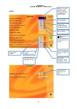
Page 22: ...ion quality correct function and safety The producer saves changes of parameters by password Is prohibited to make unqualified changes Important note The value of parameters on the pictures below is ONLY SAMPLES Actual setting depend on the type of boiler Producer and qualified service can make changes only Next page ...

Page 23: ...trol 22 Next page Temperatures Previous page Maximum boiler temperature Minimum exhaust temperature for heating Button for activate electric heating Maximum exhaust temperature Temperature for activate pump Temperature for activate bypass pump ...

Page 24: ...tion Time for pre heating of ignition spiral without fan Control temperature Note Control temperature is important for fire control Fan revolution Time limit for ignition Time for stabilisation of fire Fuel for stabilisation of fire Time spiral activation during stabilisation of fire Time for prolong of stabilisation of fire Time feeder F1 during burn on fuel ...

Page 25: ...Button to select programs for settings Parameters for chosen program above Actual program for fix power Note Is possible to set here but main settings is on the main menu Time period in which automatic boiler is not actively burning Time fire life Setting temperature Time ...

Page 26: ...iler control 25 Modulation Feeders Note If it is set 0 then there is no control of the motor PID regulation recommended Parameters for regulations Time count impulses Allowed errors On time feeder F2 before F1 Off time feeder F2 of F2 ...

Page 27: ...Workbook 4 Controller SIGMATEK Boiler control 26 Cleaning Ash removing USB Time window setting ...

Page 28: ...Workbook 4 Controller SIGMATEK Boiler control 27 Load from USB Save on USB ...

Page 29: ...Workbook 4 Controller SIGMATEK Boiler control 28 3 3 2 Menu heating circuits Button for open window for addition heating circuits Button for confirmation ...

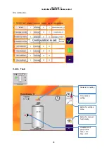
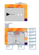
Page 30: ...Controller SIGMATEK Boiler control 29 After confirmation 3 3 2 1 Tank Demand for heating Time window setting Button for settings menu Button for manual functionality Visualisation of pump status Green On Grey Off ...

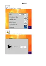
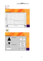
Page 31: ...Workbook 4 Controller SIGMATEK Boiler control 30 Function for settings of parameters Function for manual control of pump ...

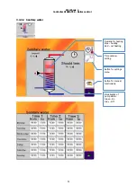
Page 32: ... SIGMATEK Boiler control 31 3 3 2 2 Sanitary water Demand for heating Blue heating Red not heating Time window setting Button for settings menu Button for manual functionality Visualisation of pump status Green On Grey Off ...

Page 33: ...Workbook 4 Controller SIGMATEK Boiler control 32 ...

Page 34: ...emand for heating Blue heating Red not heating Time window setting Button for settings menu Button for manual functionality Visualisation of pump status Green On Grey Off Button for ekviterm parameters Servo location White closed Black opened Servo control White Off Green On ...

Page 35: ...Workbook 4 Controller SIGMATEK Boiler control 34 ...

Page 36: ...Workbook 4 Controller SIGMATEK Boiler control 35 i ...

Page 37: ...antee number 2 4 The user is obliged to demonstrate that the product was maintained in regular intervals which are described in the chapter MAINTENANCE Regular annual maintenance has to be done by trained person who is also responsible for the record of it within 14 days list is part of manual service intervention or repaired has to be correctly recorded and sanded to a manufacturer 5 Every notifi...

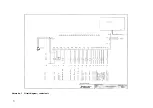
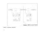
Page 38: ...37 Picture No 7 Circuit diagram control unit ...

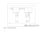
Page 39: ...38 Picture No 8 Circuit diagram module HZS 533 ...

Page 40: ...39 Picture No 9 Circuit diagram HZS 533 HZS 53 ...

Reviews: