Pompetravaini TRSK 2002/1 Operating Manual Download Page 17

Operating manual liquid ring vacuum pumps TRVK - TRSK 

17 

9.3 - INSTALLATION SCHEMATICS FOR LIQUID RING VACUUM PUMPS 

The working principle of the vacuum pump requires a continuous flow of fresh and clean liquid that enters the pump at 
the service liquid connection identified by the letter “Z” (see following chapter). The liquid is discharged together with the 
handled gas through the pump discharge flange. 


Take care of their disposal according to the laws into force and to a safe local environment management.


The quantity of said liquid will vary with pump size and degree of working vacuum (see performance curves). 
The service liquid absorbs the compression heat generated by the pump compression therefore its temperature will rise 
by some 4°C to 8°C according to working point. 
There are three basic installation schematics listed below that may be considered, depending upon the quantity of service 
liquid that is desired and possible to be recycled. 


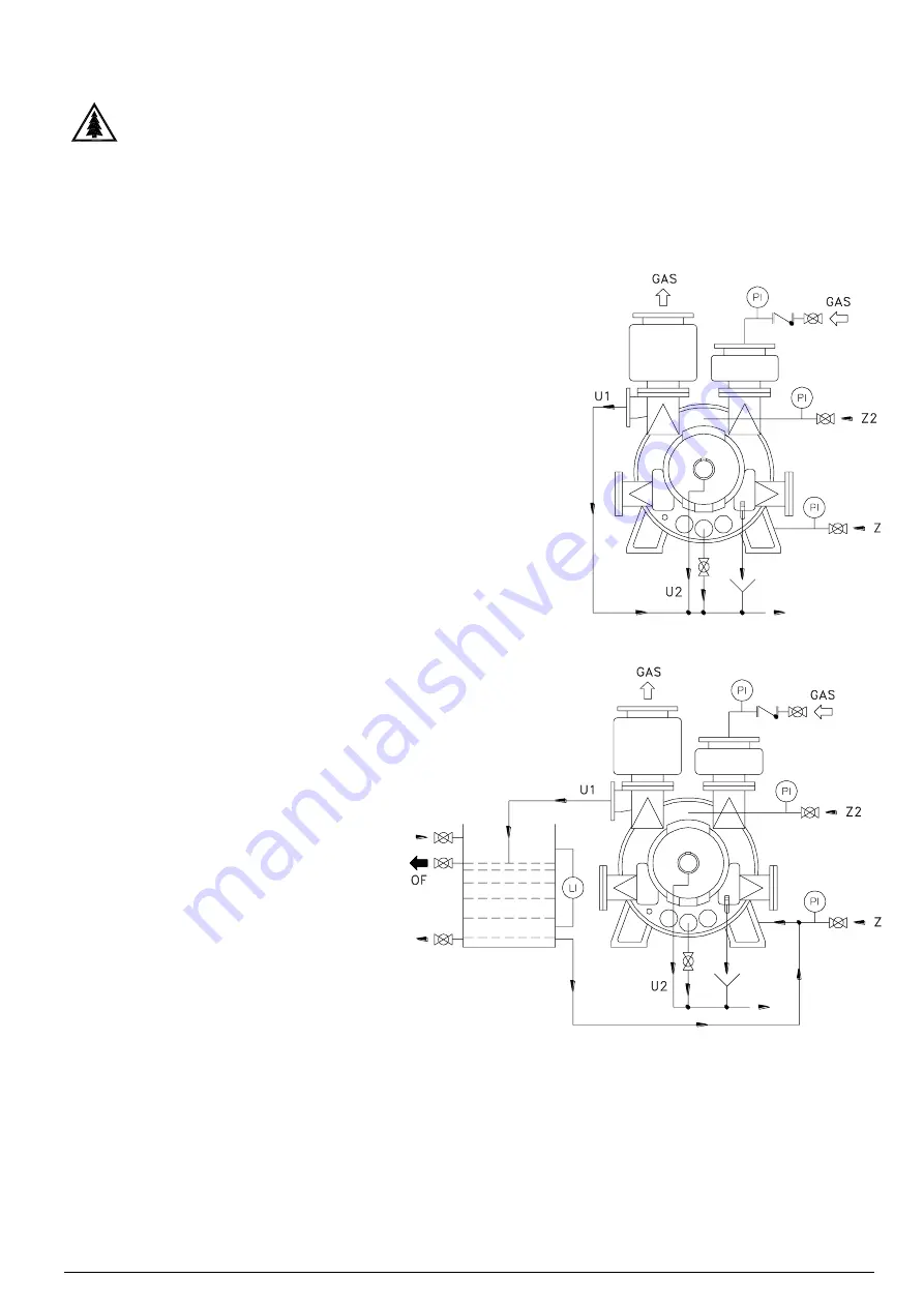
9.3.1 - Service liquid: Once-through system (no recovery) 

All the service liquid is supplied from an external source. 
The liquid is separated from the gas in the manifold separator and drains 
directly  through  the  discharge  connection  located  at  the  bottom  of  the 
manifold separator itself. 
This is the most common installation scheme and can be applied when it 
is  available  an  abundant  constant  flow  of  fresh  liquid  and/or  when  the 
liquid contamination problem never exist, liquid that can be harmful for the 
surrounding environment: therefore provide a proper disposal according 
to laws into force. 
The  service  liquid  should  be  supplied  at  the  pump  connection  with  a 
pressure of 0.2 to 0.4 bar maximum to avoid flooding the pump with too 
much liquid. 
If this is not possible it is recommended to install a reservoir fitted with a 
float valve, this tank is supplied with the liquid that is then pulled by the 
pump as required by the operating conditions. 
The liquid level in the reservoir should be approximately at the pump shaft 
centreline. 
Schematic fig. 18 illustrates the once-through system. 
 

9.3.2 - Service liquid: Partial recovery system 

This  type  of  installation  is  used  where  it  is 
desired  to  minimise  the  use  of  fresh  service 
liquid. 
The service liquid enters and leaves (take care 
of  its  eventual  disposal  according  to  the  laws 
into  force  and  to  a  safe  local  environment 
management)  the  pump  same  as  the  once 
through  system,  however  part  of  the  liquid  is 
recycled from the discharge separator and the 
balance  is  continuously  supplied  from  an 
external source. The excessive liquid is drained 
through the separator overflow connection. 
The temperature of the mixed liquid supplied to 
the pump will be higher than the temperature of 
the  make-up  liquid.  Its  final  temperature  will 
depend upon the amount of the recycled liquid. 
It  is  important  to  remember  that  with  higher 
service 

liquid 

temperature 

the 

pump 

performance  will  decrease  (see  chapter  17) 
with the possibility of operating the pump in the 
cavitation area. 
When the separator tank is installed along side 
of  the  pump  (our  type  HSP),  its  liquid  level 
should not be above the pump shaft centreline. 
Schematic fig. 19 illustrates the system with partial recovery of the service liquid. 
 
C   

=  Cooling circuit 

OF  

=  Overflow 

U1  

=  Service liquid discharge 

U2  

=  Packing flushing liquid discharge 

Z   

=  Service liquid inlet 

Z2  

=  Inlet flushing liquid for packing 


Fig. 18 

Fig. 19 

Summary of Contents for TRSK 2002/1

Page 1: ... NA4 IS VUOC IN00 Rev 3 8_11 2020 OPERATING MANUAL LIQUID RING VACUUM PUMPS TRVK TRSK ...

Page 2: ...led with an electrical motor of Pompetravaini supply or customer supply placed on the market after the 15th of August 2018 fell within the limits of application of the Directive As a consequence conforming to article 14 of the 2012 19 UE Directive of the European Parliament of the 4th of July 2012 Pompetravaini Spa is registered on the Italian list of EEE manufacturer The electrical pump assembly ...

Page 3: ... 9 3 3 Service liquid Total recovery system 9 4 Pump engineering data 10 Check list prior to start up 11 Starting operating and stopping procedures 11 1 Start up 11 2 Operation 11 3 Shut down 12 Operating maintenance 13 Bearings mechanical seals and packed stuffing boxes maintenance 13 1 Bearings 13 2 Mechanical seals 13 3 Packed stuffing boxes 13 3 3 Adjustment of the packing 13 3 2 Replacement o...

Page 4: ...gs contact POMPETRAVAINI or the authorised local representative 1 2 READING THE INFORMATIONS MARKED ON PUMP S NAMEPLATES AND SERVICE CARDS The machinery Directive 2006 42 EC and the ATEX Directive 2014 34 EU require the marking of certain information on the pump s nameplates The pump nameplate must be applied so that it is not easily removable and remains legible for long time Furthermore accordin...

Page 5: ...o a use in a Zone classified for Dust There could be another string for example for the Technical File 8TCx19R006 if necessary There are also symbols identifying some particularities of the pumps and systems The EC symbol identify a product subject to the Machinery Directive 2006 42 CE The trash bin symbol identify a product subject to the WEEE Directive 2012 19 EU The symbol EX identify a pump th...

Page 6: ...sessing that all other equipment and accessories supplied and included in the bill of material are compliant with CE and ATEX requirements and guarantee a degree of protection equal to or higher than that of the pump they are coupled to Each device instrument or accessory has been selected and assembled by Pompetravaini according to the manufacturer s instructions and so as not to compromise its c...

Page 7: ...ed to the pump must NEVER be under pressure or vacuum when maintenance or repair is carried out NOTE There are materials in the pump that may be hazardous to people suffering from allergies Maintenance and operating personnel should consult the tab 1 for such materials Take care of their eventual disposal according to the laws into force and to a safe local environment management Tab 1 MATERIAL US...

Page 8: ...centrifugal force assumes the shape of the impeller casing The progressive change of volume between the 2 vanes the impeller hub and the liquid ring first creates a vacuum and then a compression of the gas in the B C area till the gas is discharged together with a portion of the liquid through the discharge port C D The lost liquid must then be replenished 4 2 SERVICE LIQUID PROPERTIES For a good ...

Page 9: ... department Take immediate actions to dispose of eventual packaging parts that may generate injuries or risks for example edges nails splinters etc and of materials subjected to controlled and differentiate disposal for example plastic cartoon polystyrene materials etc according to the laws into force and to a safe local environment management according to the laws into force and to a safe local e...

Page 10: ...Operating manual liquid ring vacuum pumps TRVK TRSK 10 90 OK NO Fig 2 Fig 4 Fig 1 Fig 3 ...

Page 11: ...ximum rigidity to prevent vibrations and distortions It is recommended the use of a fabricated baseplate manufactured with rigid U shaped channel fig 16 illustrates an example When the pump has been purchased without the electric motor it is then required to select the proper motor before proceeding to the installation of the unit Selection of motor must consider the following maximum power absorb...

Page 12: ...sert the perforated metal sheet coupling guard inside the lantern so that the coupling is accessible from one of the lateral openings Couple the electric motor to the pump lantern engaging the two coupling halves hands may reach the coupling halves through the lateral opening see fig 7 tighten the assembly with bolts supplied with the unit and install the supporting foot when applicable see fig 6 ...

Page 13: ...late and bring the two coupling halves together with approx 2 mm gap between them keeping the motor axially aligned with the pump shaft In the event the two shaft heights do not align proper shimming under the pump or motor feet will be required Mark the motor and or pump anchoring bolt holes Remove motor and or pump drill and tap the holes clean and mount pump and or motor in place and lightly ti...

Page 14: ...the guard should not be greater than 2 to 3 mm see fig 15 2 to 3 mm Fig 15 7 4 BELT DRIVE ALIGNMENT PROCEDURE If the pump is fitted with belt drive it is necessary to verify the tension of the belts at the first start up and periodically at least every 6 months as described see figure 16 Disconnect the electrical power from the motor of the pump with the PUMP STOPPED remove the guard from the pull...

Page 15: ...hich are supplied with the pump or systems must be connected and handled in accordance with the instructions supplied by their respective manufacturers When the pump is coupled on baseframe carry out the ground connection also for the baseframe on the preposed position with screw or through hole marked by the ground connection symbol Remove a portion of the paint on the connection point to ensure ...

Page 16: ... B The pump series TRVK TRSK are supplied with a discharge manifold capable of separating gas from the service liquid If it is desired to implement separation in a separate tank it is necessary to close the service liquid discharge connection located at the manifold 9 2 ACCESSORIES Listed below are common accessories that may be supplied with the pump or added at a later date Non return valve chec...

Page 17: ...upplied at the pump connection with a pressure of 0 2 to 0 4 bar maximum to avoid flooding the pump with too much liquid If this is not possible it is recommended to install a reservoir fitted with a float valve this tank is supplied with the liquid that is then pulled by the pump as required by the operating conditions The liquid level in the reservoir should be approximately at the pump shaft ce...

Page 18: ... to from to TRVK 1502 1 850 565 880 30 55 200L 250M 260 410 TRVK 1503 1 1043 590 920 45 90 225M 280M 320 650 TRVK 2003 1 705 500 740 55 110 250M 315S 410 1000 TRVK 2503 1 790 370 660 75 160 280S 315L 550 1160 TRVK 3003 1 1060 370 530 132 250 315M 355M 1100 1700 TRVK 3503 1 1005 270 470 160 315 315L 355L 1160 1850 TRVK 4003 1 1130 240 400 200 500 315L 450 1270 3020 TRVK 5003 1 1295 210 330 315 630 ...

Page 19: ... first start up and before every start up if pump or motor has been removed from the installation for maintenance or other reasons see chapter 7 2 Prior to starting the pump verify that all auxiliary components are available ready for use and where required they are in the open position i e double mechanical seals are pressurised with buffer liquid cooling liquid to heat exchanger is open etc and ...

Page 20: ...is consistently handling the application for which it was selected The operation of the pump should be without abnormal vibrations or noises if any of these problems is noticed the pump should be stopped immediately search for the cause and make the necessary corrections It is good practice to check the pump motor alignment the running conditions of the bearings and of the mechanical seals see cha...

Page 21: ...em Systems that handle condensable will experience a rise in the level of the service liquid in the separator The excessive liquid will be overflowed through the overflow valve or connection 13 BEARINGS AND MECHANICAL SEALS MAINTENANCE WARNING The maintenance must be carried out with the pump turned off and the electrical power or other driving mechanism must be disconnected The power should only ...

Page 22: ...or special constructions contact Pompetravaini 13 3 PACKED STUFFING BOXES Pumps fitted with packed stuffing boxes require packing flushing either from an external source or directly from the pumped media through pump internal passages This liquid is necessary to remove the friction heat generated between the shaft and the packing For the exact locations and dimensions of the flushing connections s...

Page 23: ...stablish a steady dripping at low temperatures Packing adjustment is required when the liquid leakage increases When adjustment is no longer possible the packing material should be replaced with new one see following chapter In the event the pump remains out of service for more than 6 months it is recommended to replace the packing rings prior to start up 13 3 2 REPLACEMENT OF THE PACKING RINGS Th...

Page 24: ...alve to a lower vacuum 8 High service liquid flow Reduce the service liquid flow adjust the by pass valve 9 High back pressure Check the discharge line for obstructions or high friction losses reduce the back pressure to maximum 0 1 bar 10 Wrong pump motor assembly Verify that the base surface is level and that all pump feet are resting on the surface add spacers if required 11 Mechanical seal fai...

Page 25: ...on Avoid damaging other system components After pump repairs re install following the steps from Assembly and Alignment procedures and after see the applicable chapters 16 SPARE PARTS When ordering the pump it is good practice to also order the necessary spare parts especially when there are no stand by pumps in the installation This will minimise unnecessary down times in the event of pump failur...

Page 26: ...P x 3600 Isothermal compression heat QK mV x r Condensation heat QR mg x cp x ΔTa Cooling heat generally negligible ignored in calculation of QT m v mass condensed incoming vapour in kg h mg mass incoming gas in kg h P absorbed power at operating point in kW cP gas specific heat in kJ Kg x K r heat of vaporisation in kJ Kg ΔTa differential temperature in K between incoming gas TG and service liqui...

Page 27: ...Operating manual liquid ring vacuum pumps TRVK TRSK 27 17 3 UNIT CONVERSION TABLE Absolute pressure Vacuum Dry air flow at 15 C Saturated vapour flow Saturated water temperature Vaporization heat ...

Page 28: ...Operating manual liquid ring vacuum pumps TRVK TRSK 28 blank page ...

Page 29: ...Operating manual liquid ring vacuum pumps TRVK TRSK 29 blank page ...

Page 30: ...Operating manual liquid ring vacuum pumps TRVK TRSK 30 blank page ...

Page 31: ...mpatibilità elettromagnetica EMC Directive 2014 30 UE Direttiva Bassa Tensione LVD 2014 35 UE EN 60204 1 2018 Sicurezza del macchinario Equipaggiamento elettrico delle macchine Safety of machinery Electrical equipment of machines EN 60034 1 2010 Macchine elettriche rotanti Valutazione e prestazioni Rotating electrical machines Rating and performace I Questa dichiarazione perde validità nel caso in...

Page 32: ...ITALY Continuing research of POMPETRAVAINI results in product improvements therefore any specification may subject to change without notice 20022 CASTANO PRIMO Milano ITALY Via per Turbigo 44 Zona Industriale Tel 0331 889000 Fax 0331 889090 www pompetravaini com S p A ...

Reviews: