background image


Operating manual for centrifugal pumps AT - TB… - MC… - TC… - TMA 

9

Even if the machine is properly stored, as described in the instructions above, in case of long term storage the 
following instructions must be taken into account. 
 
After a storage period of 6 months the lubricant should be replaced completely. 
 
In case of a storage period longer than 12 months, the machine shall be carefully checked and inspected
before installation. Following actions should be considered particularly: 
-  complete replacement of lubricants 
-  inspection of the bearings, they should be cleaned if necessary 
-  inspection of O-rings and gaskets (it is recommended to replace them) 
-  inspection of mechanical seal integrity (replace if necessary). 


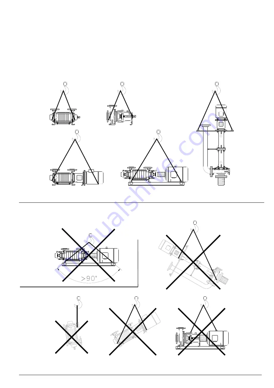
Fig. 1 


Fig. 2 

Fig. 3


OK

NO

Summary of Contents for AT

Page 1: ... Rev 2 5_05 2019 OPERATING MANUAL FOR CENTRIFUGAL PUMPS AT TB MC TC TMA ...

Page 2: ...rous for persons and environment provide their possible disposal in conformity with the laws into force and a proper environment management The present manual is not assigned for pumps subjected to the ATEX 2014 34 EU directive In case the pump is assigned in environments subjected to the application ATEX 99 92 CE directive or in case the pump is provided with a nameplate indicating the ATEX stamp...

Page 3: ...11 1 1 Submersed pump vertical design 11 1 2 Pump with flooded suction 11 1 3 Pump with suction lift from well 11 1 4 Start up a pump without back pressure at discharge side 11 1 5 Start up a pump with back pressure at discharge side 11 2 Operation 11 3 Shut down 12 Operating check list 13 Lubrication instructions 13 1 Grease lubricated ball bearings 13 2 Oil lubricated ball bearings 14 Packed stu...

Page 4: ...will be stored or installed Extreme low or high temperatures may severely damage the pump unless proper precautions are taken POMPETRAVAINI does not guarantee repairs or alterations done by user or other unauthorised personnel Special designs and constructions may vary from the information given in this manual Please contact POMPETRAVAINI should you have any difficulty NOTE Drawings appearing in t...

Page 5: ...ntact even during normal operation procedures and or maintenance see table 1 Take care of their possible disposal according to the laws into force and to a safe local environment management CAUTION Danger due to smokes or vapours In case smokes or vapours are released by the pump do not inhale and immediately stop the pump for inspection Tab 1 MATERIAL USE MAJOR RISKS Oil and grease General lubric...

Page 6: ...oxic and contaminated liquids Designed to DIN 24256 ISO 2858 standards Design with closed impeller Capacity to 300 m3 h Max pressure 16 bar Flanges PN 16 MILLS Pumps derived from the series TCH with special mixing impeller AT Self priming multistage centrifugal pumps with dual lateral channel Low NPSH requirements Capacity to 31 m3 h Max pressure 7 bar Flanges PN 40 TBH Self priming multistage cen...

Page 7: ...neric materials for STANDARD CONSTRUCTION pumps TMA Description F RA A3 Casing Ductile iron Stage casing Cast iron Impeller Stainless steel AISI 316 ASTM CF8M Shaft Stainless steel AISI 420 Bearing frame Cast iron For detailed information on materials of construction standard or special for pumps TCD TCK MEC TBK and TBAK please contact POMPETRAVAINI or your local representative In case the metalli...

Page 8: ... opening communicating with the inside of the pump must be properly plugged For removing the pump from the installation see chapter 17 Operate provided with apposite protective devices 6 STORAGE INSTRUCTIONS After receipt and inspection the unit if not immediately installed the unit must be repackaged and stored in the best way For a proper storage proceed as follows store the pump in a location w...

Page 9: ...ricant should be replaced completely In case of a storage period longer than 12 months the machine shall be carefully checked and inspected before installation Following actions should be considered particularly complete replacement of lubricants inspection of the bearings they should be cleaned if necessary inspection of O rings and gaskets it is recommended to replace them inspection of mechanic...

Page 10: ...ill minimise vibrations or torsion of the pump baseplate or frame It is generally preferred to have a concrete base or sturdy steel beams It is important to provide adequate anchor bolting for the pump frame or baseplate to be firmly attached to the foundations see fig 4 ANCHOR BOLT CONCRETE SPACER BASEPLATE Fig 4 Concrete pads and other concrete works must be aged dry and clean before the pump as...

Page 11: ...ks and or excessive vibrations should be controlled by means of expansion joints flexibles etc having same size as the piping PIPING SUPPORT JOINT 2 PUMP SUCTION 2 PUMP SUCTION PIPING SUPPORT JOINT PIPING FROM BELOW PUMP PUMP PIPING FROM ABOVE Fig 5 7 2 1 Suction piping see fig 5 and 6 To prevent loosing pump priming absolutely avoid formation of air pockets in the suction piping This piping there...

Page 12: ...in pressure Carry out sealing tests provided with apposite protective devices When the installation has been completed it is necessary to test the piping for both static pressure and vacuum Testing should be carried out in accordance to the applicable standards for the piping function and the operating pressures NON RETURN VALVE FOOT VALVE FILTER PRESSURE GAUGE VALVE ISOLATING SUCTION FLOODED pomp...

Page 13: ...15 for more details Only for pumps TCD 2 SP series is necessary to arrange an external flushing for the mechanical seals Quench like Directly or with a seal tank by means of a vegetable or mineral oil compatible with the pumped oil see fig 10A and 12 This is required to guarantee a proper lubrication and cooling of the mechanical seal and Viton radial seal rings to avoid the possible leakage towar...

Page 14: ...ion double tandem mechanical seal flushing outlet d2 1 Threaded connection mechanical seal chamber cooling heating liquid inlet d2 2 Threaded connection mechanical seal chamber cooling heating liquid outlet d3 1 Threaded connection flushing liquid inlet from outside for double back to back mechanical seal or for single mechanical seal construction d3 2 Threaded connection double back to back mecha...

Page 15: ...MA 15 Fig 9 CONNECTIONS AND HOOK UPS FOR FLUSHING Pumps series MC TC Standard connections and hook ups Pumps series MC TC Connections for designs C R RR R2 B Pumps series MC TC Connections for designs T U2 Where provided only d2 2 d2 1 d4 1 d4 2 d4 1 d6 ...

Page 16: ...NS AND HOOK UPS FOR FLUSHING Pumps series TCD Standard hook ups and connections Only for TCD 2 SP Pumps series MCU CH n s group 3 and 4 Standard hook ups and connections Pumps series TCH and TCN group 5 Standard hook ups and connections for Double back to back mechanical Seals ...

Page 17: ...OOK UPS FOR FLUSHING Pump series TCK Standard connections and hook ups NOTE d19 on both side for gr 2 Pump series MCM Standard connections and hook ups Pumps series TBH C TBH KC AT KC TBA C Standard hook ups and connections Pumps series TBH CT AT CT Connections for cooling or heating ...

Page 18: ...S FOR FLUSHING Pumps series TBH KC 2T AT KC 2T Connections for mechanical seals flushing cooling or heating Pumps series TBA C 2T Connections for mechanical seals flushing cooling or heating Pump series TBK Standard connections and hook ups Pump series TBAK Standard connections and hook ups ...

Page 19: ... CONNECTIONS AND HOOK UPS FOR FLUSHING Pumps series TMA 31 and 32 C and R Standard hook ups and connections Pumps series TMA 31 and 32 T Connections for cooling or heating Pumps series TMA 40 and 50 B R R2 Connections for mechanical seals flushing cooling or heating ...

Page 20: ...Fig 12 CONNECTIONS AND HOOK UPS FOR FLUSHING Pumps series MC TC API Plan 11 Recycle directly from pump casing or via cooling Pumps series MC TC Single or Double mechanical seal flushing with Seal Tank Pumps series TCD SP Mechanical seal flushing with Seal Tank ...

Page 21: ...structions for PUMP MOTOR ON BASEPLATE are listed on paragraph 8 3 steps 7 1 8 5 9 10 11 For pump driven with V BELT please consult POMPETRAVAINI for possible information 8 2 ALIGNMENT PROCEDURE FOR MONOBLOCK AND FOR PUMP MOTOR ASSEMBLY ON BASEPLATE The pump motor assembly is properly aligned by POMPETRAVAINI prior to shipment It is however required to verify the alignment prior to the start up Mi...

Page 22: ... Fig 15 PREPARATION TO ASSEMBLY ON MONOBLOCK DESIGN COUPLING GUARD FLEXIBLE COUPLIG Fig 16 CHECKING ALIGNMENT ON MONOBLOCK DESIGN 3 Applying slight hand pressure to the coupling guard rotate it so that one opening of the lantern is accessible see fig 16 4 Rotate by hand the coupling through the lateral opening of the lantern to make sure the pump is free 5 With a proper spacer check the distance b...

Page 23: ... Dial Indicators if readily available SET SCREW HALF COUPLING HALF COUPLING SET SCREW S ØA Fig 20 X Fig 21 Fig 22 Y2 Y1 If the maximum value of X is higher than that listed in the tab 2 for the given coupling size it will be required to correct the alignment by using decimal shims under the pump or motor feet NOTE the optimal values have to be considered half of the reported data When the measured...

Page 24: ...pplies to the specific pump see fig 23A 9 ELECTRICAL CONNECTIONS DANGER Electric danger Electrical connections must be made exclusively by qualified personnel in accordance with the instructions from the manufacturer of the motor or other electrical components and must adhere to the local National Electrical Code Always ground the motor verifying it is properly wired It is advisable to have an ele...

Page 25: ...nded and protected Is the position of the pump switch off button evident accessible and clear The piping system has been flushed of any foreign particles welding impurities etc Have all piping and pump obstruction been removed All connections and piping are leak proof and there are no external forces or moments applied to the piping or pump flanges Pump and motor are properly lubricated if require...

Page 26: ...d with apposite protective devices When the thermal fluid exits the air cock without any air or gas bubbles even after turning the pump rotor it means that the whole pump is full of liquid therefore close the air cock 11 1 3 Pump with suction lift from well In this case the pump must be primed fully open the isolating valve in suction piping If the pump is self priming and it has been previously f...

Page 27: ... the flow regulating valve at pump discharge prior to stopping the pump Avoid the use of instantaneous shut off valves such as solenoid valves These can cause severe pump damage If the piping has not been fitted with non return valves it is required to close the shut off valves in sequence to prevent emptying the piping Close first the isolating valve at discharge and then at suction side If the n...

Page 28: ...mps series flanges size 40 and 50 have ball bearings that during assembly are already lubricated with high quality grease with working temperature limits 30 C 140 C The bearings used in a pump normal operating conditions must be carefully cleaned and newly greased after approximately 2000 2500 working hours using a good lubricating grease quality check the Disassembly assembly instructions for the...

Page 29: ...ted oil the frequency of oil changes should be increased Bearing temperature should not exceed 85 C in normal conditions of operations and ambient temperatures Overheating could be caused by too much oil coupling misalignment excessive vibrations and or bearing wear It is recommended to periodically check the oil pH which will indicate the oil stability and the oxidation grade consult the supplier...

Page 30: ... stopping before handling the unit If the pump still contains some fluid it may suddenly start to rotate once again Take precautionary measures by draining the pump or closing the pipes by mean of a valve Remove protections only in case of maintenance Operate only provided with apposite protective devices Purpose of mechanical seals is to retain handled product inside the pump in the area where th...

Page 31: ...ections on the tank Sometimes this adjustment is required because the rotation of the mechanical seal and at times peculiar seal design generates an hydraulic pressure that could be opposite and higher than the natural 0nly in field check one can be assured of the correct liquid circulation Monitoring the pressure in the seal tank with pressure switches or pressure gauges and or controlling the li...

Page 32: ...ilable upon request API Plan 61 and 62 System Plan 61 see fig 31 includes a bushing on the back of the seal at atmospheric pressure side single or double to hold the bulk of the liquid in the event of accidental failures The bushing requires a minimum clearance over the shaft therefore the liquid is NOT sealed completely but most of it will be retained in case of a sudden seal breakage Drain and v...

Page 33: ...Plan 52 Fig 31 Example of SINGLE mechanical seal with QUENCH API Plan 01 61 NOTE Continuous flushing is not possible Fig 32 Example of SINGLE mechanical seal with QUENCH API Plan 01 62 Drenaggio Sfiato Bussola di sicurezza senza contatto Pressione max superiore di 0 3 bar alla pressione atmosferica Tenuta a labbro strisciante Pump working pressure Max pressure 0 3 bar over the atmospheric pressure...

Page 34: ...mospheric pressure in case of double seals in series TANDEM Tab 4 LIQUID FLOW FOR COOLING OR HEATING JACKETED SEAL HOUSING maximum pressure for liquid circuit is 3 5 bar referred to water and ambient temperature In case of heating circuit the allowed maximum temperature is 135 C Flow tolerance 25 CAUTION Flow for cooling or heating of jacketed pump casings design U2 pump series MC TC see fig 34 ca...

Page 35: ...ets in the suction line Modify the layout of suction piping 6 Air enters the suction line Check the piping sealing areas 7 The pumped liquid is emulsified with air Install a reservoir or tank before the pump to de aerate the liquid 8 The suction lift or and suction pressure is more than anticipated and therefore the pump cavitates Reset the suction lift to the original value Increase the piping di...

Page 36: ...o the normal level using proper quality lubricants 30 The power absorbed is too high Decrease the power consumption by identifying the cause 31 Pump is running dry Reinstate the correct working conditions 32 Pumped liquid or the flushing liquid to the seals is dirty and or not adequate Install a filter in the flushing lines Change flushing fluid 33 There are excessive shaft vibrations and deflecti...

Page 37: ...safety glasses gloves safety shoes etc disconnect the electrical power supply and if required disconnect the electrical cables from the motor close the pump inlet and outlet isolating valves let the pump cool down to ambient temperature if is pumping hot liquids adopt safety measures if the pump has been handling dangerous liquids drain the pump body of the pumped liquid through the draining conne...

Page 38: ...ings etc 1 1 2 2 3 30 Bushes 3 4 50 Shaft protection sleeves 2 2 3 Neck rings 1 1 2 2 3 30 Packing rings 16 16 24 24 24 32 40 Gaskets for pump casing Set 4 6 8 8 9 12 150 Other gaskets Set 10 100 Mechanical seals Rotating part 2 3 4 5 6 7 90 Stationary part Rotating part gasket 6 8 8 10 150 Stationary part gasket Springs 1 1 1 1 2 2 20 Bearing housing groups complete with shaft bearings covers sea...

Page 39: ...rticular observation first the pump must reach a value of minimum capacity Qm correspondent to the partialized capacity of the valve such to guarantee a correct operation without problems of liquid evaporation or excessive radial loads on the shaft then the pump by totally opening the valve will reach the value of nominal capacity Qn and therefore the value of maximum operating torque NOTE In this...

Page 40: ...itres sec 0 4719 Litres min m3 h 0 06 C F M Litres min 28 32 Litres min C F M 0 0353 C F M m3 h 1 698 To convert To obtain Multiply by To convert To obtain Multiply by Capacity Litres m3 0 001 U S Gal Litres 3 785 Litres Ft3 0 0353 U S Gal m3 0 003785 Litres U S Gal 0 02641 U S Gal Ft3 0 0133 Litres Imp Gal 0 219 U S Gal Imp Gal 0 0832 m3 Litres 0 001 Imp Gal Litres 4 545 m3 Ft3 35 3 Imp Gal m3 0 ...

Page 41: ...ss V2 4 5 4 5 7 7 PUMP MODEL TMA Noise level Lp LW dB A Vibration level class 2 poles 2 poles 31 3 72 84 V1 31 4 31 5 31 6 31 7 31 8 31 9 31 10 31 11 31 12 31 13 31 14 31 15 32 3 32 4 32 5 32 6 32 7 32 8 32 9 32 10 32 11 32 12 32 13 32 14 32 15 40 3 76 89 V2 40 4 40 5 40 6 40 7 40 8 40 9 40 10 40 11 40 12 40 13 40 14 40 15 50 3 50 4 50 5 50 6 50 7 50 8 50 9 50 10 50 11 50 12 PUMP MODEL TC Noise le...

Page 42: ...1 73 85 402 403 404 405 406 407 408 501 75 88 502 503 504 505 506 507 508 651 77 90 652 653 654 655 656 657 658 WARNING 2 poles motors PUMP MODEL TBH Noise level Lp LW dB A Vibration level class 4 poles 4 poles 201 70 82 V1 202 203 204 205 206 207 208 291 292 293 294 295 296 297 298 301 302 303 304 305 306 307 308 311 312 313 314 315 316 317 318 401 74 86 402 403 404 405 406 407 408 501 75 88 502 ...

Page 43: ...64 72 1 1 55 63 50 58 54 62 60 68 54 62 48 56 56 64 64 72 1 5 57 65 53 61 54 62 63 71 56 64 57 65 56 64 71 79 2 2 57 65 55 61 55 63 63 71 60 68 59 67 57 65 71 79 3 58 66 57 65 55 63 67 75 60 68 62 70 57 65 74 82 4 60 68 57 65 58 66 69 77 64 72 62 70 62 70 74 82 5 5 60 68 57 65 61 69 72 81 64 72 62 70 66 74 75 83 7 5 60 68 63 71 61 69 72 81 64 72 66 74 69 77 77 85 11 63 71 64 72 68 78 74 82 66 75 6...

Page 44: ... dB A Power dB A INSTALLATION SERVICE Inside Outside Continuous Intermittent Explosive area MOTOR type Frame No Poles No Revolutions RPM Absorbed power Amp Installed Power kW HP Frequency Hz Supply Volt Enclosure IP Insulation class Absorbed Power kW HP COMMENTS NA4 IS CENT GB00 PRINTED IN ITALY Manuale Centrifughe Inglese Continuing research of POMPETRAVAINI results in product improvements theref...

Reviews: