Operating manual for centrifugal pumps AT - TB… - MC… - TC… - TMA
13
Pump series TCK
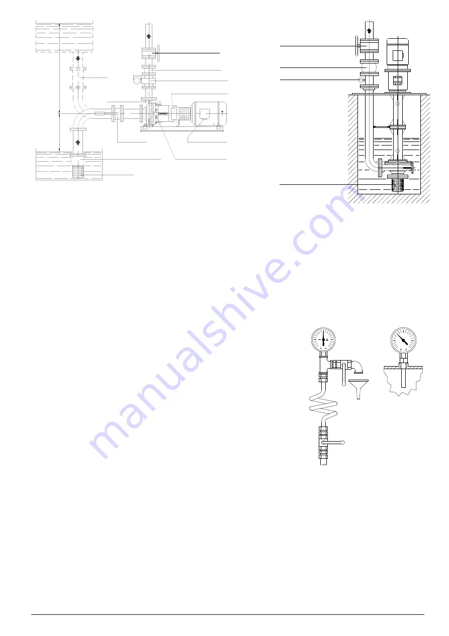
NON RETURN VALVE
FLOW CONTROL VALVE
PRESSURE GAUGE
FILTER
Pump series MC... - TC... - VERTICAL construction
Fig. 6B
7.3 - ACCESSORIES AND AUXILIARY CONNECTIONS
Depending on the application accessories may be installed to test the pump performance (instrumentation to measure
pressure, temperature, capacity, etc.) and/or for necessary operations (cooling, heating, flushing of seals, etc.).
When accessories are required the following should be considered:
a)
Pressure and vacuum gauges must be properly anchored and connected at the measuring points located at pump
flanges or near the flanges, using approx. 8 mm. diameter tubing with “pig tail” configuration to alleviate pressure
fluctuations.
For safety purposes, isolating and vent valves should be fitted before these instruments (see fig. 7).
b)
Temperature gauges should be installed with thermowells selected for the
specific purpose and fitted in strategic locations where the reading is required
(see fig. 8).
c)
Every pump is fitted with draining connections at the pump casing.
If required, pump drain and mechanical seals leakages can be piped to a
container located nearby on the floor or (if available) to the drain catch basin
for the total installation.
The pump draining piping should be fitted with an isolating valve and both
should be suitable for the pumps maximum operating pressure.
d)
Cooling, heating, flushing of mechanical seals and other piping must be
connected only to the designated connections located on the pump (see fig.
9-10-11-12 and chapter 15 for more details).
Only for pumps TCD/2-SP series is necessary to arrange an external flushing for
the mechanical seals (Quench-like). Directly or with a seal tank by means of a
vegetable or mineral oil compatible with the pumped oil (see fig. 10A and 12).
This is required to guarantee a proper lubrication and cooling of the mechanical
seal and Viton radial seal rings, to avoid the possible leakage towards outside and the intake of air into the process. Also
to prevent the formation of air bubbles, preventing a proper lubrication, which can lead to the damaging the sealing, in
case of high temperature, could even lead to dangerous combustion.
All tubing and connections must be a minimum of same size as the connection on the pump.
Insulation, if required, must be limited to the pump body, leaving all other components such as bearing frame and
motor uncovered for heat dissipation.
e)
Controlling the minimum capacity.
When the pump operates near the shut-off with almost no flow, almost all the motor power is transformed into thermal
energy which is absorbed by the pumped liquid.
If the capacity is less than the minimum recommended (10-15% of pump capacity at its best efficiency point) not only
will there be excessive load on the pump support and bearings but the liquid could evaporate resulting in damage to
the impellers and wear rings with possibility of the pump seizing.
To prevent these problems it is recommended the installation of a minimum flow valve in the discharge piping, right
after the pump but before the flow regulating valve.
Fig. 7
°C
Fig. 8
FLOODED
SUCTION
SUCTION
LIFT
FILTER
POWER SUPPLY
ISOLATING
VALVE
HEAT SENSOR
(FOOT VALVE)
RECORDER
STRAINER
NON RETURN VALVE
FLOW METER OR FLOW SWITCH
ACCELOROMETER SENSOR
PRESSURE GAUGE
FLOW CONTROL VALVE


