


3032
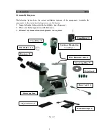
2.2 Assembly Steps
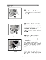
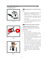
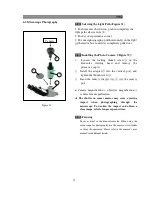
Figure 3
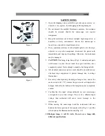
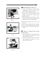
2-2-1 Installing and Replacing the Lamp (Figure 3
)
)
)
)
Use the specified halogen lamp: 6V30W
Wrap the bulb (1) with gauze or lint free paper; press the
pins (2) into the socket (3) in the lamp house.
When replacing the lamp turn the main switch to “O” (off)
and remove the power cord. Allow the lamp, lamp house
and the adjacent areas to sufficiently cool before handling.
The lamp will become very hot and will cause burns.
Do not touch the halogen bulb with your hands.
Fingerprints on the bulb may shorten the bulb life or
interfere with the illumination. Clean all fingerprints
with a dry soft cloth.
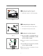
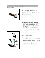
2-2-2
Installing the
Condenser
Illumination
Assembly
(
(
(
(
Figure 4
)
)
)
)
1.
Insert the condenser illumination unit (1) into the
bracket (2).
2.
Turn the condenser illumination unit at clockwise
about 90 until the “AS” mark of filter holder
③
is
facing forward.
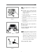
3.
Keep the screws the of condenser illumination
unit and the holes of the bracket aligned. Tighten the
screws with the supplied hexagon wrench.
4.
Insert BNC connector cable
④
into the BNC
connector plug
⑤
.
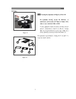
2-2-3 Installing the Lamp House (Figure 5)
Keep the BNC connector plug
①
and the lamp house
pin
②
aligned. Also keep the bolt
③
and the condenser
jack
④
aligned. Then gently push the lamp house into
the illumination unit until they are completely
connected.
3
Figure 4
Figure 5
3
2
1
4
1
2
3
1
3
5
6
4
2
4


