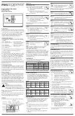
08
6. Operating Menus
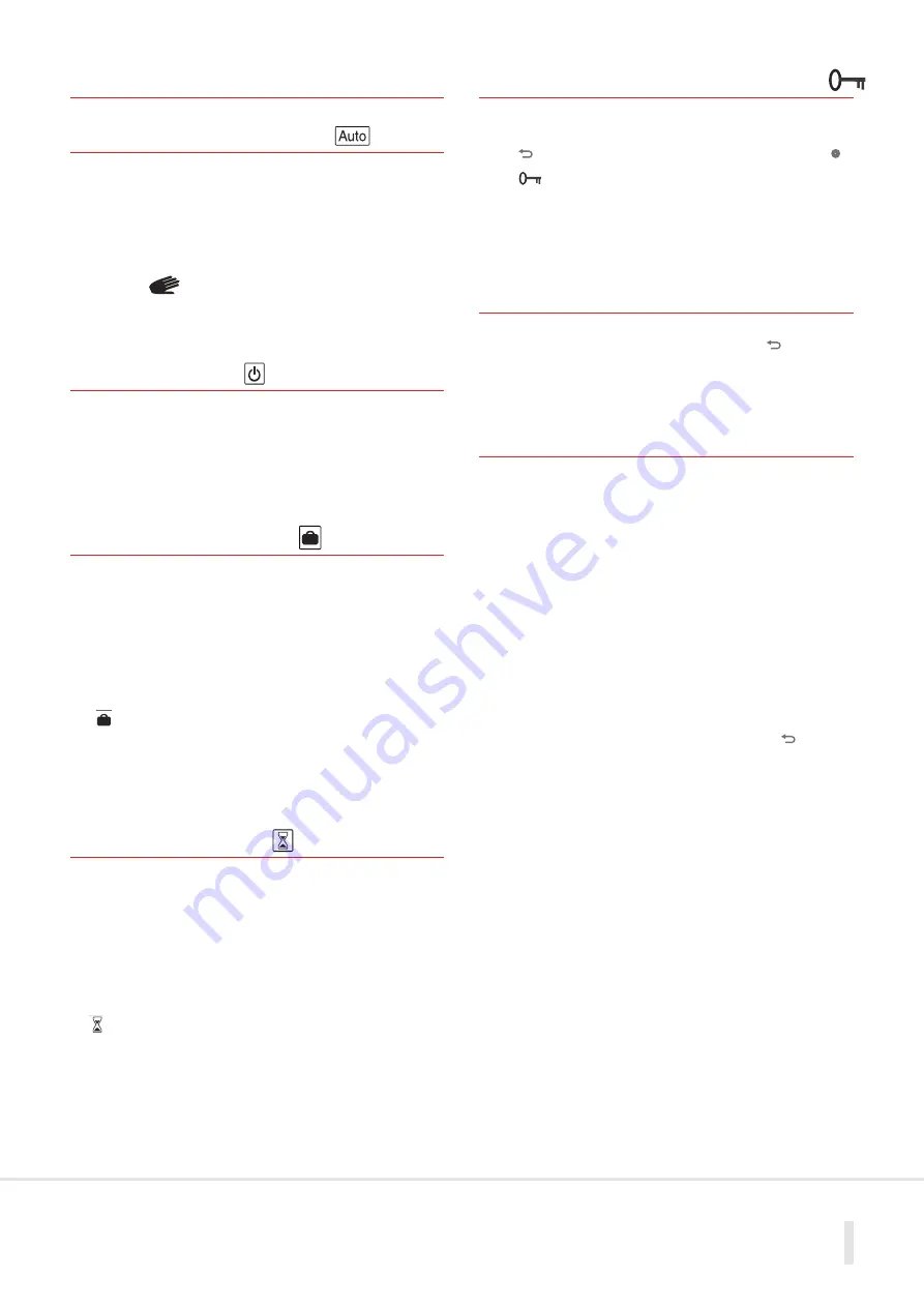
6.1 Automatic Mode
In this mode the thermostat will follow the chosen program
(Built-in or User defined) according to the time and the Comfort
and Setback temperature settings.
You can easily override the current temperature of the program
by pressing on the
(-)
and
(+)
in Auto mode at any time.
The current setting will blink to show you that you can change it.
A small hand will be display to show you have overridden
Auto function, however Auto timings will return at the next time
change.
6.2 Off Mode
Use this mode if you wish to turn off your thermostat.
Frost protection is automatically provided and a minimum
temperature of 7.0°C will be maintained.
(This temperature can be changed, contact your installer or check
advanced menu).
6.3 Holiday Mode
The Holiday mode allows you to adjust the temperature for a
period of days:
The display will show “
no
”, press
(OK)
.
- Adjust the duration in day “
d
” with
(-)
or
(+)
, press
(OK)
to
validate (adjustable 1 to 99 days).
- Adjust the temperature setting (default value 10°C) with
(-)
or
(+)
, press
(OK)
to start the function.
The icon will blink and the number of days remaining is
displayed until the end of the period.
If you want to stop the holiday function before the end of the
duration adjust the day period on “
no
”.
6.4 Timer Mode
The Timer mode allows you to adjust the temperature and the
duration for a particular time.
This function can be used should you need to override the set
program for a short time.
Adjust the duration in hours “
H
” if below 24H, then in days “
d
”
with
(-)
or
(+)
, press
(OK)
to validate (adjustable 1 hour to 99
days).
Adjust the setting temperature with
(-)
or
(+)
, press
(OK)
to start
the function (default value 22°C).
The logo will be blink and the number of hours/ days left is
displayed until the end of the period.
If you want to stop the timer function before the end of the
duration adjust the period on “
no
”.
6.5 Keyboard Lock Function
Use this function to prevent changes to the settings:
- To activate the key lock function, first press maintain the escape
key
( )
and then press simultaneously on the edition key
(
•
)
.
- The “ ” icon will now be displayed on
the screen.
- Repeat with the same procedure to unlock
the keyboard.
7. External Connections
If accessories (wet room sensor) are installed on your thermostat,
you can see all values by pressing the escape key
( )
(scroll function).
7.1 Settings for using
the Wet Room Sensor
Note: The thermostat has hidden menus for calibration etc.
These are described in the full version of this document on the
Polypipe website
www.ufch.com
The connection of the wet room sensor allows adjacent wet
rooms to be controlled from a thermostat outside the room.
However this sensor can also be used as a floor sensor to control
floor surface temperatures where sensitive floor coverings are
installed.
In the settings menu the sensor(s) are referred to as follows:
Air
=
The room thermostat
Flr
=
External sensor used as a floor sensor
Ext
=
External Sensor used as air sensor
FL.1
= Both sensors used. Air temp with floor regulation
To access the Menu to set this, hold the escape key
( )
for
10 seconds.
You will then access the hidden installer menu.
Starting with menu 21, use the navigation keys to reach menu
23 REGU Air.
Press
(OK)
to toggle between the options with the
(-)
and
(+)
keys and verify with
(OK)
.
If you choose FLR or FL.1, use the navigation keys to reach Menu
26 (FL:Lo) Floor Low limit can be set. Then Menu 27 (FL:Hi) Floor
High limit can be set.
Continue to menu 35
(END)
and
(OK)
to exit the settings Menu.


