Pololu DMC01 User Manual Download Page 13

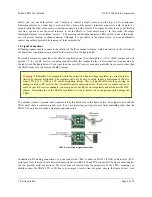
Perhaps most noticeably, these parameters help determine how the channel inputs affect the motors. Motor speed is
scaled linearly (or parabolically, if the channel is set as parabolic using the “parabolic channels” configuration
parameter) from 0 at a channel input of

deadband

to max speed at a channel input of

maximum

. In the

other direction, motor speed goes from 0 at

neutral-deadband

to max speed at

minimum

. Motor speed is 0 for

channel inputs between

neutral-deadband

and

deadband

, and motor speed is at a maximum for channel

inputs greater than

maximum

or less than

minimum

. Motor direction is determined by the side of neutral the

channel input is on, and notions of forward and reverse can be switched on a channel by channel basis using the
“reversed channels” configuration parameter.

4.c. General RC Information

When the channel inputs are RC servo pulses, the update rate of the channel values is determined by the pulse-train
frequency of your RC receiver. Typically this is 50 Hz (each channel updates every 20 ms). The TReX can handle
channel pulse-train frequencies of 10 Hz to 125 Hz.

The TReX measures the width of RC servo pulses with 12-bit resolution and an accuracy of 1 us. The raw channel
value is provided as a 12-bit number in units of 0.4 us, so a raw channel value of 2500 can be physically interpreted
as a pulse width of 2500×0.4 =1500 us. Servo pulse widths typically range from 1 ms to 2 ms, with a neutral value
of 1.5 ms. This would correspond to raw channel values of 2500, 5000, and 3750, respectively. The TReX can
handle pulse widths as short as 0.5 ms (raw channel value 1250) and as long as 2.5 ms (raw channel value 6250). If
a channel reading is considered to be an error, the raw channel value will be 0xFFFF (65535 in decimal). Errors
result from pulse widths outside the acceptable range and from pulse trains with frequencies outside of the
acceptable range. If a signal ceases on a channel, that channels value will stop updating until approximately 150 ms
elapse, at which point the channel’s raw value will become 0xFFFF. It will remain as such until valid signals are
once again detected on the line.

As a safety feature, you can designate channels as

required

using the “required channels” configuration parameter.

If a required channel goes for more than 500 ms without receiving a valid RC servo pulse and the TReX is in RC
mode, the TReX will enter safe-start mode (see

Section 4.e

). By default, the TReX only requires channel one.

If you are not using all five channels, you can optionally ignore unused channels via the “ignored channels”
configuration parameter. Ignored channels are treated as fixed at their neutral values (no matter what signals their
lines receive).

4.d. General Analog Information

When the channel inputs are analog voltages, the update rate of the channel values is approximately 50 Hz (each
channel updates every 20 ms or so). Each channel’s value is the result of a 16-sample average of analog-to-digital
conversions.

The TReX measures analog voltages with 10-bit resolution. The raw channel value is provided as a number ranging
from 0 to 1023, where 0 corresponds 0 V and 1023 corresponds to 5 V. Your channel source can be as simple as the
output of a potentiometer whose inputs are the channel’s associated power (make sure the BEC jumper is in place)
and ground connections.

Unlike with RC signals, the TReX has no way of telling if a channel is receiving a valid analog signal. A
disconnected channel will still produce a result when run through the analog-to-digital converter. This poses two
potential problems:

1. If your analog signal source gets disconnected from your TReX, the TReX could drive the motors in

unexpected and potentially dangerous ways. Because of this, please be very careful when operating the
TReX in analog mode.

2. Unused channels can impact behavior of the TReX in undesirable ways. You may not plan on using the flip

or override channels, but leaving them disconnected could result in their floating to a value that would enable

Pololu TReX User's Guide

© 2001–2009 Pololu Corporation

4. RC/Analog in Detail

Page 13 of 22

Summary of Contents for DMC01

Page 1: ...General RC Information 13 4 d General Analog Information 13 4 e Safe Start Mode 14 5 The Serial Interface 15 5 a Serial Communication Settings 15 5 b Serial Command Protocols 15 5 c Serial Command Li...

Page 2: ...ermines whether the motors are controlled by the channel inputs or the serial interface this channel allows you to switch between autonomous and human control at will The serial interface can switch i...

Page 3: ...your projects and about your experience with the TReX motor controller You can contact us http www pololu com contact directly or post on our forum http forum pololu com Tell us what we did well what...

Page 4: ...through the VIN GND connector terminals VIN should be between 6 and 16 V and your power source must be able to supply the current your motors will be drawing The TReX can supply peaks of 30 A and up...

Page 5: ...to ensure you do not solder the diode in backwards You should not solder a diode to your bidirectional motors You may find it beneficial to solder 0 1uF capacitors across all of your motors terminals...

Page 6: ...ure you remove the BEC jumper Warning This middle Vcc column is tied to the output of a linear voltage regulator so current output is limited by thermal dissipation The regulator will only be able to...

Page 7: ...ls motor 2 This jumper may be added or removed on the fly Battery Elimination Circuit BEC a k a Vcc Jumper When this jumper is in place the middle column of channel input pins is connected to Vcc 5 V...

Page 8: ...r LED is located on the top board When it is brightly illuminated the TReX is receiving power and is running Note that the power LED can occasionally glow dimly when the TReX is unpowered if it is con...

Page 9: ...dicates that serial is in control of the motors i e serial override is active or the TReX is in serial mode While serial is in control of the motors the green LED acts as a serial packet received indi...

Page 10: ...microcontroller Ungrounding the SO pin will cause the TReX to startup as normal removing the mix jumper will put the TReX into firmware upgrade mode which will cause the red and green LEDs to start al...

Page 11: ...ess or if the channel variance is too large the TReX will not learn the channel Learning mode phase 2 neutral learning report Once phase one is through the TReX will flash its status LEDs five times t...

Page 12: ...nnel value falls below a certain threshold If your controller is not calibrated this channel may not function as intended Channel 5 Enable disable serial override Serial override gives serial control...

Page 13: ...will stop updating until approximately 150 ms elapse at which point the channel s raw value will become 0xFFFF It will remain as such until valid signals are once again detected on the line As a safet...

Page 14: ...be simultaneously met 1 All required channels must have a valid signal This only applies when the TReX is in RC mode since it s not possible to have an invalid analog signal Required channels are dete...

Page 15: ...ands result in two way data transfer An additional consequence of the RS 232 circuit is everything you send to the TReX using the RS 232 connection will be echoed back to you as you re transmitting it...

Page 16: ...l is compatible with the serial protocol used by our other serial motor and servo controllers As such you can daisy chain a TReX on a single serial line along with our other serial controllers includi...

Page 17: ...rks is beyond the scope of this document but you can find a wealth of information using Wikipedia http en wikipedia org wiki Cyclic_redundancy_check The quick version is that a CRC computation is basi...

Page 18: ...a speed perspective You can find an example of this Section 5 f 5 f CRC Generation Algorithm in C The CRC algorithm is typically defined as a bit wise operation however it is possible to rewrite the a...

Page 19: ...s It is possible to reset the TReX to its default serial settings using the following jumper sequence 1 Power off your TReX 2 Attach the channel mix jumper 3 Attach the learning mode firmware update j...

Page 20: ...s this will increase the rate at which you can communicate with and control your TReX Updating Firmware To update the firmware you need to put your TReX into firmware update mode and then send the new...

Page 21: ...initiate the firmware update If all goes correctly you will be prompted to confirm that you want to erase your current firmware and you will then see a progress bar showing you the status of the uploa...

Page 22: ...mpleted the 8 steps above so that the green status LED is flashing once per second you are ready to upload the new firmware file First transmit the character s This will erase the current firmware Nex...

Reviews: