Polaris 2005 SPORTSMAN 400 Servise Manual Download Page 268

ELECTRICAL

10.8

3. When the desired time increment is displayed,

release the button and wait for the wrench to stop

flashing. When the wrench stops blinking, your

service hours are set.

NOTE:

If you scroll past the intended number, hold

the button down until the count turns over to

0

. You

can then reset the number.

Turn Service Interval OFF:

1. If the service interval is enabled (functioning) on

your ATV and you wish to turn it off, toggle to the

service interval mode.

2. Press and hold the mode button for approximately

7 seconds until the word

OFF

appears in the Rider

Information Center. The service interval is now off.

3. To enable (turn on) the service interval mode,

repeat the steps above in “Setting Service Interval

After Countdown”.

Change Service Interval Time:

If you would like to change the service interval time,

(for example change the interval from 50 hrs. to 55

hrs.). Follow the steps below:

1. While in the service interval mode, press and hold

the mode button for approximately 7 seconds until the

word

OFF

appears in the Rider Information Center.

2. Wait 5 seconds and then press the mode button in

until the wrench icon flashes. Press the mode button

again to set the desired service increment. Release

the button and wait for the wrench icon to stop

flashing. The new service interval is now set.

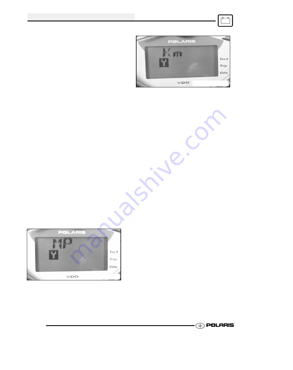
Screen 6: Miles/Kilometers

toggle, The display in

the trip meter and odometer can be changed to

display either kilometers or miles. The current display

mode will be shown as “KM” or “MP”. To change, hold

in the mode button until the letters flash, then press

and release the button once. When the display stops

flashing, the mode has been set.

MP = Miles

Km = Kilometers

*NOTE:

As long as you are in the diagnostic mode,

the wrench icon will remain lit.

*NOTE:

To leave the diagnostic mode, turn the key

switch off and on.

Summary of Contents for 2005 SPORTSMAN 400

Page 1: ...SPORTSMAN 400 500 6 59 0 18 31 99194 31 25 3ULQWHG LQ 86 2005 SPORTSMAN 400 500 6 59 0 18 31 25 31 9919425 SPORTSMAN 400 500 6 59 0 18 31 99194 31 9919425 Cvr_9919425 7 28 04 10 19 AM Page 1...

Page 2: ...ndex is provided at the end of the manual for location of specific page numbers and service information Keep this manual available for reference in the shop area At the time of publication all informa...

Page 3: ...tes special precautions that must be taken to avoid personal injury or ATV or property damage NOTE A NOTE provides key information to clarify instructions Trademarks Polaris acknowledges the following...

Page 4: ...GENERAL MAINTENANCE ENGINE CARBURETION CLUTCHING FINAL DRIVE BODY AND STEERING TRANSMISSION BRAKES ELECTRICAL...

Page 5: ...Location 1 2 Publication Numbers 1 3 Paint Codes 1 3 Replacement Keys 1 3 General Specifications Sportsman 400 500 1 4 1 6 Special Tools 1 7 1 12 Standard Torque Specifications 1 13 Decimal Equivalent...

Page 6: ...erial No Body Style Check Digit World Mfg ID This could be either a number or a letter Whenever corresponding about an engine be sure to refer to the engine model number and serial number This informa...

Page 7: ...dustries com ATV PAINT INFORMATION FRAME COLOR All P067 Medium Gloss Black 9440 8520147 COLD WEATHER KITS FOR 4 CYCLE ATVS Engine Heater PN 2871507 ACCESSORY ENGINE HEATER REPLACEMENT KEYS Replacement...

Page 8: ...pacity 180 lbs 81 6 kg Towing Capacity 1225 lbs 555 6 kg Hitch Tongue Weight 120 lbs 54 4 kg Body Style SPIRIT MODEL 2005 Sportsman 500 MODEL NUMBER A05MH50 ENGINE MODEL 500 Category Dimension Length...

Page 9: ...ry Model Amp Hr Maintenance Free 12 Amp Hr Starting Electric Recoil Backup Instrument Cluster LCD Drivetrain Transmission Type Drum Shift H L N R P Transmission Capacity 32 oz Front Gearcase Capacity...

Page 10: ...m Battery Model Amp Hr Maintenance Free 12 Amp Hr Starting Electric Recoil Backup Instrument Cluster LCD Drivetrain Transmission Type Drum Shift H L N R P Transmission Fluid Capacity 32 oz Front Gearc...

Page 11: ...Tool 5 2870506 Clutch Puller 6 9314177 Clutch Holding Wrench 6 2871358 Clutch Holding Fixture 6 2870341 Drive Clutch Spider Removal and Install Tool 6 2870654 Clutch Offset Alignment Tool 6 2870913 D...

Page 12: ...stituted with a similar tool if available Polaris reccommends the use of Polaris special tools when servicing any Polaris product Standard Tools and Engine Tools PU 45432 Caliper or A Basic Caliper Ba...

Page 13: ...2872105 Water Pump Seal Puller PV 35667 A Cylinder Leak down Tester 2200634 Valve Seat Reconditioning Kit Clutch PVT Tools 2870506 Drive Clutch Puller 2870913 Driven Clutch Puller 2870654 ATV Clutch A...

Page 14: ...01379 EBS Bushing Replacement Kit 2870338 Spider Nut Socket 2871358 Clutch Holding Fixture 2871025 Clutch Bushing Replace Tool Kit Suspension Tools 2870871 ATV Ball Joint Tool Kit 2871071 Shock Body H...

Page 15: ...ssion Tools 2871702 Shaft Drive Transmission Front Gearcase Tool Kit 2871351 Shock IFP Depth Tool 2871282 Bearing Seal Driver 50 mm Electrical Tools PV 43568 Fluke 77 Multimeter 2870836 Battery Hydrom...

Page 16: ...ctrical Tools 2870630 Timing Light 2871745 Static Timing Light Harness 2460761 Hall Sensor Probe Harness PV 39991 Peak Reading Adapter PV 37453 Christie Se Sulfating Multi Battery Charger PV 63070 Chr...

Page 17: ...3 5 0 60 6 9 10 32 31 3 6 49 5 6 68 7 8 Torque ft lbs Nm 1 4 20 5 7 8 11 12 16 1 4 28 6 8 10 14 14 19 5 16 18 11 15 17 23 25 35 5 16 24 12 16 19 26 29 40 3 8 16 20 27 30 40 45 62 3 8 24 23 32 35 48 50...

Page 18: ...11 32 R 3 8 13 32 13 32 0 0995 0 0937 0 1285 0 125 0 166 0 161 0 196 0 234 0 277 0 265 0 3125 0 3125 0 3437 0 339 0 375 0 406 0 406 3 32 3 32 1 8 1 8 11 64 5 32 13 64 15 64 9 32 17 64 5 16 5 16 11 32...

Page 19: ...Cubic centimeters cc x 0 061 Cubic inches cu in Imperial pints Imp pt x 0 568 Liters l Liters l x 1 76 Imperial pints Imp pt Imperial quarts Imp qt x 1 137 Liters l Liters l x 0 88 Imperial quarts Im...

Page 20: ...rotational direction g Gram Unit of weight in the metric system gal Gallon ID Inside diameter in Inch inches Inch Pound In lb 12 in lbs 1 ft lb kg cm 2 Kilograms per square centimeter kg m Kilogram m...

Page 21: ...em 2 16 2 17 Compression Test 2 18 Battery Maintenance 2 19 Coolant System Maintenance 2 19 2 21 Air Filter Service 2 21 2 22 Air Box Sediment Tube Service 2 22 Breather Filter 2 23 Recoil Housing 2 2...

Page 22: ...il level begins to rise Monitor the oil level and if it continues to rise discontinue use and determine the cause or see your dealer Maintenance Chart Key The following symbols denote potential items...

Page 23: ...nt every 2 years Headlamp tail lamp Daily Check operation apply dielectric grease if re placing E Air filter main element Weekly Inspect replace as needed Recoil housing Weekly Drain water as needed c...

Page 24: ...e Cable ETC Switch 50 H 6 M 310 500 Inspect adjust lubricate replace if necessary J E Choke cable 50 H 6 M 310 500 Inspect adjust lubricate replace if necessary E Carburetor air intake ducts flange 50...

Page 25: ...ect replace as needed J E Ignition Timing 100 H 12 M 620 1000 Inspect Wiring 100 H 12 M 620 1000 Inspect for wear routing security apply dielectric grease to connectors subjected to water mud etc J Cl...

Page 26: ...871534 60 40 Coolant Quart 12 Count NOTE Each item can be purchased separately at your local Polaris dealer Part No Description Additives Sealants Thread Locking Agents Misc 2870585 Loctitet Primer N...

Page 27: ...e purchased at your local Polaris dealer 2859061 Sportsman 500 Maintenance Kit Oil Filter 3 Qts of 0W 40 oil EBS Drive Belt PVT Cover Seal Spark Plug Instruction Sheet 2873554 Sportsman 400 500 Oil Ch...

Page 28: ...case Front Drive Shafts Right Side View Engine Recoil Transmission Rear Storage Compartment Front Storage Compartment Rack Gas Cap Gear Shifter Brake Lever Ignition Key Choke Brake Fluid Reservoir Ins...

Page 29: ...Annually 6 Propshaft Yoke Premium U Joint Grease PN 2871551 Locate fittings and grease 3 pumps maximum Annually NOTE Refer to Page 2 6 for the Polaris Lubricant Identification table More often under s...

Page 30: ...or any damaged or loose nuts bolts or fasteners S Engine coolant check for proper level at the recovery bottle FRONT GEARCASE LUBRICATION The gearcase lubricant level should be checked and changed in...

Page 31: ...lug 8 mm hex 4 Fill with the recommended fluid amount 5 oz or to the bottom of the fill plug hole threads See ILL 3 Plug Threads Fill with 5 oz lubricant or bottom of fill plug threads Front Gearcase...

Page 32: ...t of the machine using a proper lifting device or automotive approved ramps S This will ensure that the oil in the transmission is properly drained 2 Remove the drain plug and wipe the magneticend cle...

Page 33: ...ifter Shifter Mount Shift Linkage Rod THROTTLE INSPECTION Check for smooth throttle opening and closing in all handlebar positions Throttle lever operation should be smooth and lever must return freel...

Page 34: ...nut Firmly grasp the rubber boot and tighten until the choke slides freely but stays out when pulled PILOT SCREW The pilot system supplies fuel during engine operation with the throttle valve closed...

Page 35: ...the PET 2100DX PN 8712100DX or the PET 2500 PN 8712500 4 Set idle speed to 1200 RPM Always check throttle cable freeplay after adjusting idle speed and adjust if necessary 5 Slowly turn mixture screw...

Page 36: ...EM WARNING Gasoline is extremely flammable and explosive under certain conditions S Always stop the engine and refuel outdoors or in a well ventilated area S Do not smoke or allow open flames or spark...

Page 37: ...d clamps onto fuel lines with arrow pointed in direction of fuel flow 6 Install clamps on fuel line 7 Turn fuel valve ON 8 Start engine and inspect for leaks CARBURETOR DRAINING The carburetor float b...

Page 38: ...nder Leakage Service Limit 10 Inspect for cause if leakage exceeds 10 ENGINE MOUNTS Inspect rubber engine mounts A for cracks or damage Check engine fasteners and ensure they are tight A A A SPARK PLU...

Page 39: ...ad of lead antimony allows the battery acid to be fully absorbed For this reason a Low Maintenance battery case is dark and the cell caps are not removable since there is no need to check electrolyte...

Page 40: ...t over tighten hose clamps at radiator or radiator fitting may distort causing a restriction to coolant flow Radiator hose clamp torque is 36 in lbs 4 Nm RADIATOR GRILL SCREEN B A 1 Check radiator A a...

Page 41: ...bottle has run dry or if overheating is evident the level in the radiator should be inspected and coolant added if necessary WARNING Never remove the pressure cap when the engine is warm or hot Escapi...

Page 42: ...Be sure the element covers entire surface of main filter without folds creases or gaps 11 Reinstall filter on main filter mount Place filter clamp over the assembly and tighten NOTE Apply a small amou...

Page 43: ...box pre filter is in place and maintained properly Never operate the engine without the pre filter RECOIL HOUSING Recoil Drain B Recoil Handle Location S Drain the housing periodically to remove moist...

Page 44: ...e level on the dipstick Do not overfill NOTE Rising oil level between checks in cool weather driving can indicate moisture collecting inthe oil reservoir If the oil level is over the full mark change...

Page 45: ...ng on new filter with a film of engine oil Check to make sure the O ring is in good condition 17 Install new filter and turn by hand until filter gasket contacts the sealing surface then turn and addi...

Page 46: ...engine at IDLE for 10 20 seconds 3 Remove the vent line clamp The oil pump will now be properly primed and ready for field operation Note If the system is primed properly you should hear some air rel...

Page 47: ...end of intake valve stem and clearance adjuster screw 2 Using a 10 mm wrench and a screwdriver loosen adjuster lock nut and turn adjusting screw until there is a slight drag on the feeler gauge 3 Hol...

Page 48: ...tment be performed by an authorized PolarisMSD certi fied technician when replacing worn or dam aged steering parts Use only genuine Polaris replacement parts One of two methods can be used to measure...

Page 49: ...axle center line as possible NOTE It is important that the height of both marks be equally positioned in order to get an accurate measurement 4 Measure the distance between the marks and record the m...

Page 50: ...muffler as shown in illustration 1 Clean Out Plug Ill 1 2 Place the transmission in Park and start the engine Purge accumulated carbon from the system by momentarily revving the engine several times 3...

Page 51: ...nings could result in serious personal injury or death BRAKE SYSTEM INSPECTION The following checks are recommended to keep the brake system in good operating condition Service life of brake system co...

Page 52: ...ake effectiveness by applying 50lb approx downward force on the pedal The top of the pedal should be at least 1 inch 25 4mm above the surface of the footrest 50 lbs 1 or greater 1 8 to 1 4 Free Play F...

Page 53: ...ever to travel throughout entire range without contacting switch body Throttle assembly clamp Align clamp edge with knurl Align throttle control assembly clamp with knurl on handlebar WHEELS Inspect a...

Page 54: ...e wheel nuts to the proper torque listed in the table CAUTION If wheels are improperly installed it could affect vehicle handling and tire wear On vehicles with tapered rear wheel nuts make sure taper...

Page 55: ...h chapter FRONT REAR STORAGE COMPARTMENTS The front and rear storage compartments are easily accessible To open the front compartment turn the latch handle to the horizontal position on both sides To...

Page 56: ...IN OUT control controls the direction of the cable for the winch IN pulls the cable into the winch and OUT feeds the cable out of the winch Mini Rocker Switch IN OUT Winch Control The winch control l...

Page 57: ...Located Under Right Front Cab Area Winch Connecting Wires or Pic of quick connect and locations Under Right Side Front Fender Contactor mounts on Splash Guard The Red wire 6 Ga with the yellow crimp c...

Page 58: ...ure washers may force water past seals Stabilize the Fuel Fill the fuel tank Add Polaris Carbon Clean Fuel Treatment or Polaris Fuel Stabilizer Follow the instructions on the container for the recomme...

Page 59: ...in storage See Chapter 10 for instructions Engine Anti Freeze Test engine coolant strength and change if necessary Coolant should be replaced every two years See Page 2 19 for the proper test procedur...

Page 60: ...MAINTENANCE 2 40 MAINTENANCE SCHEDULE Service Date Hours Miles Service Performed Serviced By...

Page 61: ...tion Oil Flow 3 11 3 12 EH50PL Engine Exploded View 3 13 EH50PL Engine Top End Disassembly 3 14 3 23 EH50PL Valve Seat Service 3 23 3 26 EH50PL Cylinder Head Assembly 3 26 3 31 EH50PL Engine Bottom En...

Page 62: ...e 14mm 14 17 19 23 Nm Oil Filter Pipe Fit ting 20mm 36 43 49 59 Nm Oil Hose Fitting 1 8 Pipe Thread 6 5 11 9 15 Nm Hard Metal Oil Line Banjo Fitting N A 11 16 ft lbs 15 21 Nm Oil Pump 6mm 5 6 5 7 9 Nm...

Page 63: ...il clearance Std 0022 0035 055 090 mm 0022 0035 055 090 mm Limit 0039 10 mm 0039 10 mm Cylinder Head Surface warpage limit 0020 05 mm 0020 05 mm y Standard height 3 870 98 3 mm 3 870 98 3 mm Valve Sea...

Page 64: ...hand fit at 68 F 20 C Piston Ring Piston ring installed gap Top ring Std 0079 0138 20 36 mm 0079 0138 20 36 mm g g g p p g Limit 039 1 0 mm 039 1 0 mm Second i Std 0079 0138 20 36 mm 0079 0138 20 36...

Page 65: ...the top The letter F or must always be toward the flywheel side of the engine The other numbers are used for identification as to diameter length and design Four stroke engine rings are rectangular p...

Page 66: ...y bottle hose from coolant filler 3 Connect a Mity Vact PN 2870975 to radiator and pressurize system to 10 PSI The system must retain 10 lbs of pressure for five minutes or longer If pressure loss is...

Page 67: ...Mechanical Seal Puller PN 2872105 to replace mechanical seal with engine in frame ENGINE REMOVAL TYPICAL 1 Clean work area 2 Thoroughly clean the ATV engine and chassis 3 Disconnect battery negative c...

Page 68: ...lines to force air out of system 4 Again remove radiator cap and slowly add coolant to top of fill neck 5 Start engine and observe coolant level in the radiator Allow air to purge and top off as nece...

Page 69: ...t the end of each stroke S Release the hone at regular intervals and inspect the bore to determine if it has been cleared and to check piston fit NOTE Do not allow cylinder to heat up during honing Th...

Page 70: ...LUBRICATION EH50PL Oil Type Polaris Premium 4 Synthetic PN 2871281 or API certified SH 5W30 oil Capacity Approximately 2 U S Quarts 1 9 l Filter PN 3084963 Filter Wrench PV 43527 Drain Plug Screen Fit...

Page 71: ...ge in the head Oil enters the camshaft through the PTO L journal The camshaft journals cam lobes and rocker arms are lubricated through holes in the camshaft The oil lubricates the cam chain and sproc...

Page 72: ...Small End Bearing Cylinder Sleeve Main Bearing PTO Large End Bearing Crank Pin Crankshaft Screen Fitting Bottom of Tank EH50PL Oil Flow Chart Top of Oil Tank Union Fitting Lower Oil Jet Union Fitting...

Page 73: ...ENGINE 3 13 EH50PL ENGINE EXPLODED VIEW Crankcase Cylinder Cylinder Head Crankshaft and Piston Valvetrain A...

Page 74: ...engine slowly watching camshaft sprocket marks and the mark in the timing inspection hole 4 Align single TDC mark on flywheel with projection in inspection hole and the cam sprocket pin facing upward...

Page 75: ...Spring Free Length 2 320I 5 9 cm 4 Measure free length of tensioner spring Replace spring if excessively worn Compare to specifications 5 Replace entire tensioner assembly if any part is worn or dama...

Page 76: ...rts and visually inspect surface Compare to specifications 6 Subtract rocker shaft O D from rocker arm shaft support I D This is the oil clearance Compare to specifications 7 Inspect rocker adjuster s...

Page 77: ...e to prevent it from falling into the crankcase Inspect for Areas of Tooth Wear or Damage Sprocket Teeth 9 Inspect cam sprocket teeth for wear or damage Replace if necessary Decompressor Ball Retainer...

Page 78: ...he camshaft until the actuator ball is in the lowest position and install the release lever shaft If Camshaft Is Installed In The Engine 4 Use a small magnet to draw the actuator ball outward or rotat...

Page 79: ...ompare to specifications Camshaft Oil Clearance Std 0022 0035I 055 090 mm Limit 0039I 10 mm NOTE Replace camshaft if damaged or if any part is worn past the service limit NOTE Replace cylinder head if...

Page 80: ...ENGINE 3 20 CYLINDER HEAD EXPLODED VIEW EH50PL A EH50PL...

Page 81: ...DER HEAD DISASSEMBLY WARNING Wear eye protection or a face shield during cylinder head disassembly and reassembly NOTE Keep all parts in order with respect to their location in the cylinder head A 1 U...

Page 82: ...check for bent valve stems mount valve in a drill or use V blocks and a dial indicator A B 3 Check end of valve stem for flaring pitting wear or damage A 4 Inspect split keeper groove for wear or fla...

Page 83: ...ng the valve guides and valve seats requires special tools and a thorough knowledge of reconditioning techniques Follow the instructions provided in the cylinder head service tool kit CAUTION Wear eye...

Page 84: ...lled Height Valve Guide Height 689 709I 17 5 18 0 mm 4 Place a new guide in the valve guide installation tool and press guide in to proper depth Check height of each guide above the cylinder head A NO...

Page 85: ...r 75 cutter to raise the seat When contact area is centered on the valve face measure seat width S If the seat is too wide or uneven use both top and bottom cutters to narrow the seat S If the seat is...

Page 86: ...carefully with a rotating motion to avoid damaging valve seal 5 Dip valve spring and retainer in clean engine oil and install spring with closely spaced coils toward the cylinder head 6 Place retaine...

Page 87: ...engines valves NOTE Both feeler gauges should remain inserted during adjustment of each valve 006 15 mm EXHAUST VALVE CLEARANCE 3 When clearance is correct hold adjuster screw and tighten locknut secu...

Page 88: ...upport Block PN 2870390 8 Remove dowel pins from crankcase PISTON REMOVAL 1 Remove circlip Note piston directional arrow pointing toward the right Mag side of engine 2 Remove piston circlip and push p...

Page 89: ...of the cylinder for warpage using a straight edge and feeler gauge Cylinder Warpage 002 05 mm 3 Inspect cylinder for wear scratches or damage 1 2 Down From Top of Cylinder 1 2 Up From Bottom X X Y Y X...

Page 90: ...surement obtained in Step 5 above Piston to Cylinder Clearance Std 0006 0018I 015 045 mm Piston O D Std 3 6204 3 6215I 91 970 91 985 mm PISTON ROD INSPECTION Piston Pin Bore Piston Pin Bore 9055 9057I...

Page 91: ...A difference in end gap indicates cylinder taper The cylinder should be measured for excessive taper and out of round 3 If the bottom installed gap measurement exceeds the service limit replace the ri...

Page 92: ...gear teeth on starter drive Replace starter drive if gear teeth are cracked worn or broken FLYWHEEL STATOR REMOVAL INSPECTION 1 Remove flywheel nut and washer 2 Install Flywheel Puller PN 2871043 and...

Page 93: ...h for wear or damage 7 Inspect Woodruff key for wear 8 Replace any worn or damaged parts ONE WAY VALVE The one way valve prevents oil from drainingout of the oil tank and into the crankcase when the e...

Page 94: ...o not strike the oil pump shaft at an angle or the shaft may bend causing irreparable damage Tap only lightly on the pump shaft if necessary 4 Remove the Mag RH crankcase from the PTO case OIL PUMP RE...

Page 95: ...ner and outer scavenge rotor and inspect pump shaft for wear OIL PUMP ASSEMBLY 1 Clean and dry all parts thoroughly Apply clean engine oil to all parts Do not use gasket sealer on the pump body mating...

Page 96: ...s of discoloration scoring or galling Turn the inner race of each bearing The bearings should turn smoothly and quietly The outer race of each bearing should fit tightly in the crankcase The inner rac...

Page 97: ...bearings and pump shaft bearing use a blind hole bearing puller NOTE Bearings are stressed during the removal process and should not be re used PUMP SHAFT OIL SEAL WATER PUMP MECHANICAL SEAL REMOVAL E...

Page 98: ...INSPECTION ADJUSTMENT Before reassembling the crankcase the following steps should be performed to determine the amount of crankshaft counter balancer shaft and pump shaft end play Excessive end play...

Page 99: ...record below Total Case Width 7 Measure the width of the crankshaft at the bearing seats with a micrometer or dial caliper and record Crankshaft Width 8 Subtract the Crankshaft Width measured in Step...

Page 100: ...red in Step 2 from the figure obtained in Step 5 7 Subtract the thickness of the existing shim from the result of Step 6 to determine if a different shim is needed The result must be within the specif...

Page 101: ...crankshaft and balancer gears Install the proper shim washer on the shaft 5 Inspect the oil pump sealing surface on the crankcase Apply a light film of engine oil to the surface and install the oil p...

Page 102: ...e can result in a bent water pump shaft Pump shaft replacement requires engine removal and crankcase separation Use caution while performing this procedure Make sure that the puller is parallel to the...

Page 103: ...g until the remaining portion of mechanical seal has been removed from the cases Ill 6 Pump shaft oil seal can also be replaced at this time if necessary 7 The Water Pump Install Kit PN 5131135 is req...

Page 104: ...on The tab must be positioned in the notch on the side of the piston as shown A A 3 Install the bottom rail with the gap at least 30 from the end of the expander on the side opposite the top rail gap...

Page 105: ...linder base gasket A 2 Position the Piston Support Block PN 2870390 A beneath the piston skirt to support the piston during cylinder installation 3 Apply clean engine oil to the ring compressor Snap O...

Page 106: ...reads and washers and hand tighten the bolts The following procedure must be used to torque the cylinder head properly Torque all bolts evenly in a criss cross pattern Torque bolts to 22 ft lbs 30 Nm...

Page 107: ...utward and the alignment pin notch facing directly upward A B 5 Before positioning the sprocket on the camshaft check the position of the cam sprocket alignment pin When the cam is positioned properly...

Page 108: ...ENGINE 3 48 CAMSHAFT TIMING Single TDC Mark Aligned Crankshaft to Camshaft Centerline Sprocket Alignment Pin Do Not Use Advance Marks Rotation TDC Mark Dots...

Page 109: ...the crankshaft seal Apply molybdenum disulfide grease or assembly lubricant to the crankshaft bushing 2 Install a new O Ring in the oil passage recess in the crankcase 3 Apply 3 Bond 1215 PN 2871557...

Page 110: ...faces 4 Rotate the engine until the cam lobes are pointing downward 5 Be sure the dowel pins are in place and install the rocker shaft assembly 6 Apply a light film of engine oil to the threads of the...

Page 111: ...r the recoil housing through the rope NOTE The handle must seal tightly on the recoil housing to prevent water from entering 11 Remove center bolt from recoil friction plate A 12 Inspect plate for wea...

Page 112: ...3 To complete recoil assembly 1 Route rope through guide bushing in recoil housing and into reel Tie a secure knot in end of the rope 2 Wind rope counterclockwise onto the reel as viewed from ratchet...

Page 113: ...Low compression high cylinder leakage S No spark Spark plug fouled Engine Does Not Turn Over S Dead battery S Starter motor does not turn S Engine seized rusted or mechanical failure Engine Runs But W...

Page 114: ...sticking S Air leaks in intake S Lean condition COOLING SYSTEM TROUBLESHOOTING Overheating S Low coolant level S Air in cooling system S Wrong type of coolant S Faulty pressure cap or system leaks S R...

Page 115: ...ing 4 7 Main Jet Pilot Jet Part Numbers 4 7 CV Carburetor System Function 4 Cycle 4 8 CV Carburetor Vent System 4 Cycle 4 6 CV Carburetor Operation 4 8 4 10 Pilot Screw Information 4 10 Disassembly No...

Page 116: ...Jet 27 Adjust Screw 28 Spring 29 Throttle Valve 30 Spring 31 Shaft 32 Screw 33 Throttle Shaft Assy 34 Cable Guide 35 Screw 36 Cover 37 Plunger Cap 38 Spring 39 Plunger Assy 40 Pilot Air Jet 41 Carbur...

Page 117: ...Needle Valve 21 O Ring 22 O Ring 23 Cover 24 Screw 25 Throttle Adjuster Spring 26 Washer 27 Cable Adjuster 28 Clip 29 Guide Screw 30 O Ring 31 Main Jet 32 Ring 33 Screw 34 Float Body Assy 35 Seal 36 F...

Page 118: ...LY Gas Cap Vent Line Foam Tank Foil Bracket Fuel Valve Fuel Sender Gasket 18 24 in lbs 2 3 Nm Fuel Knob Fuel Tank Fuel Valve Engine Filter Fuel Pump Carburetor Fuel Tank Vent Carburetor Vent Fitting S...

Page 119: ...Remove the side panels and front cab assembly Refer to COVER PANEL REMOVAL in Chapter 5 for details 3 Remove the gas tank cover vent hose Be sure to properly route the vent hose upon reassembly Pic 1...

Page 120: ...not overfill the tank The tank is at full capacity when the fuel reaches the bottom of the filler neck Leave room for expansion of fuel Never start the engine or let it run in an enclosed area Gasolin...

Page 121: ...3130562 135 3130563 137 5 3130564 140 3130527 142 5 3130566 145 3130567 147 5 3130568 150 3130569 152 5 3130570 155 3130571 157 5 3130572 160 3131141 162 5 3131142 165 3131143 167 5 3131144 170 31311...

Page 122: ...Diaphragm Vacuum Slide Low Pressure From Venturi CARBURETOR OPERATION CONT D When the throttle plate is opened and engine speed begins to increase the pressure in the venturi and therefore in the cham...

Page 123: ...scharged through starter outlet 6 in the the main bore FLOAT SYSTEM Fuel enters the float chamber 3 by means of the inlet pipe and passage through a screen on the back of the inlet needle seat 4 and a...

Page 124: ...ugh which the emulsified fuel must flow is determined ultimately by throttle position and vacuum slide height 1 A 5 4 3 6 7 2 PILOT SCREW The pilot system supplies fuel during engine operation with th...

Page 125: ...n tower during the float pin removal Support the float pin tower while removing the float pin This helps to prevent the float pin towers from breaking off 3 Remove inlet needle seat retaining screw al...

Page 126: ...or bacterial growth that cannot be removed Even a small amount of residue will reduce the flow characteristics of the jet 4 Verify all passages and jets are unobstructed by spraying electrical contac...

Page 127: ...alled below the E Clip Refer to parts manual for more information 4 Be sure the tab E on outer edge of diaphragm is positioned properly in the carburetor body Pilot Screw 5 Install the pilot mixture s...

Page 128: ...is important to press in on the float assembly as shown to fully seat the float assembly BST 40 BST 34 2 Measure the height from the float bowl mating surface to the top of step in float as shown Both...

Page 129: ...lear line to drain fitting Be sure line fits tightly on fitting Position hose along side of carburetor as shown 1 5 mm 060 Bowl Mating Surface 2 Open bowl drain screw by turning counterclockwise appro...

Page 130: ...s or swelling 2 To clean the valves or pump body remove the set screw and washer Remove the valve and wash with soap and water Carburetor cleaner may be used to clean the pump body when the check valv...

Page 131: ...or inlet passage G Clogged jets or passages G Float stuck holding inlet needle closed or inlet needle stuck G Float level too low G Fuel pump inoperative G Air leak at impulse line G Restricted impul...

Page 132: ...restricted idle jet Idle Too Low G Choke cable bending or incorrectly adjusted G Idle speed set incorrectly G Idle mixture screw misadjusted or damaged G Belt dragging G Ignition timing incorrect G Wo...

Page 133: ...ont Cab Fender Remove Install 5 8 Rear Cab Fender Remove Install 5 9 Radiator Screen Removal 5 10 Body Assembly Exploded View 5 11 5 12 Headlight Pod Exploded View 5 13 Handlebar Block Installation 5...

Page 134: ...location of components SPECIAL TOOLS PART NUMBER TOOL DESCRIPTION 2870871 Ball Joint Replacement Tool 2870872 Shock Spanner Wrench 2870623 Shock Absorber Spring Compression Tool 2871572 Strut Rod Wren...

Page 135: ...ter installation The inside insert A should be flush with the top of the outside insert B A B SIDE PANEL REMOVAL Side panel removal is quick and easy use the following instructions for removal and ins...

Page 136: ...aligned with the slots Then press the rear tabs into the slots FOOT WELL REMOVAL INSTALLATION 1 Remove the four plastic inserts A that secure the wheel well to the front and rear cabs See PLASTIC INS...

Page 137: ...Remove the strut tower caps B Squeeze the caps inward and lift up to remove B 3 Remove the four bolts that secure the storage rack to the frame Remove Bolts 4 Remove the two T25 screws that secure th...

Page 138: ...ce Pull Out to Remove To install the front cover place top lip of the cover into the groove in the rack then press in the bottom of the cover until the notches snap into place Lip Groove 2 Press Tabs...

Page 139: ...he four screws C T 25 into the front fender area of the storage box 2 each side 5 Install the two screws D into the rear area of the cab if removed 6 Install the two plastic inserts E into the front c...

Page 140: ...port A 3 Remove the two screws B that secure the front cab to the frame in the fuel tank mount area B A B 24 in lbs 2 7 Nm 4 Remove the side panels D refer to the SIDE PANEL REMOVAL section 5 Remove t...

Page 141: ...ulling the locks on each side and removing the connectors Lift the rear cab from the frame Remove Connectors Lock 5 Reverse the removal steps for installation REAR STORAGE REMOVAL INSTALLATION 1 Follo...

Page 142: ...l out slightly on the top of the radiator screen 2 With the top free pull out on the bottom of the screen to remove the screen 3 To install the screen simply press the tabs on the screen back into the...

Page 143: ...Cab Assembly Front Cab Assembly Seat Latch Release Storage Rear Cab Side Cover Front Cover Front Cab Wheelwell Pull UP on rear of seat and back to disengage tabs at front of seat Splash Shields Frame...

Page 144: ...2 BODY RACK EXPLODED VIEW Rack Rails Rear Rack Rear Rack Support Rack Rails Radiator Shield Support Radiator Screen Grill Panel Front Brush Guard Front Bumper Cover Box Latches Front Box Assy Strut Co...

Page 145: ...djuster S Remove two screws securing bottom half of pod E Assembly S Install bottom of pod onto handlebar and secure to brackets S Install key switch choke cable and headlight S Connect 12V power outl...

Page 146: ...Nm Install and Torque Front Bolts First NOTE There will be a slight gap on the backside of the blocks after the procedure is performed 2 The bottom handle bar block has a side with 3 holes the side w...

Page 147: ...7 19 Nm 40 45 ft lbs 54 61 Nm Steering Post Steering Post Arm Frog 1 2 NOTE To avoid damage to tie rods and other steering components be sure to install tie rod end bolts in the proper direction The s...

Page 148: ...WARNING The locking features on the existing bolts were destroyed during removal DO NOT reuse old bolts Serious injury or death could result if fasteners come loose during operation 9 Attach A arm to...

Page 149: ...17 ft lbs 24 Nm Stabilizer Support 35 ft lbs 48 Nm 30 ft lbs 41 Nm 30 ft lbs 41 Nm Lower Control Arm Orientate Bushings Correctly Rear Front Bushing Orientation 1 1 1 Upper Control Arm 35 ft lbs 48 N...

Page 150: ...ion guide for recommended service intervals 15 ft lbs 21 Nm Nut 15 ft lbs 21 Nm 18 ft lbs 25 Nm Washer Upper Pivot Ball Lower Pivot Ball Spacer Rubber Spring Retainer Spring Bolt Spacer Nut Washer Cla...

Page 151: ...orque 15 ft lbs 21 Nm BALL JOINT REPLACEMENT NOTE Refer to the illustration on the previous page for this procedure 1 Loosen front wheel nuts slightly 2 Elevate and safely support machine under footre...

Page 152: ...s that are sometimes left after a fender or cab is bent flexed or damaged WARNING The following procedure involves the use of an open flame Perform this procedure in a well ventilated area away from g...

Page 153: ...6 12 Drive Clutch Assembly 6 12 6 13 Drive Belt Tension 6 13 Drive Belt Removal Inspection 6 14 6 15 Drive Belt Installation 6 15 Clutch Alignment Offset 6 16 Drive Clutch Bushing Service 6 17 6 19 Dr...

Page 154: ...The Driven Clutch and 3 The Drive Belt The internal components of the drive clutch and driven clutch control engagement initial vehicle movement clutch upshift and backshift During the development of...

Page 155: ...fset Belt Width See Page 6 16 6 18 2 Drive and Driven Clutch Buttons and Bushings Drive Clutch Shift Weights and Pins Drive Clutch Spider Rollers and Roller Pins Drive and Driven Clutch Springs See Pa...

Page 156: ...es Warm engine at least 5 min then with transmission in neutral advance throttle to approx 1 8 throttle in short bursts 5 to 7 times The belt will become more flexible and prevent belt burning Slow an...

Page 157: ...rive belt removal 6 Remove drive clutch retaining bolt and remove drive clutch using puller Drive Clutch Puller PN 2870506 Clutch Holding Wrench PN 9314177 7 Remove driven clutch retaining bolt and dr...

Page 158: ...A B C Inner Cover Bolt Torque Rear 12 ft lbs 16 6 Nm Driven Clutch Retaining Bolt Torque 17 ft lbs 23 5 Nm Drive Clutch Retaining Bolt Torque 40 ft lbs 55 Nm 7 Install clutch offset spacer s on transm...

Page 159: ...CLUTCH EXPLODED VIEW Outer Cover Outlet Duct Cover Case Seal Inlet Duct Inner Cover Clutch Seal Bracket Drive Clutch Mark with permanent marker before disassembly Teflont coated brass bushing Teflont...

Page 160: ...se its compression rate This may result in complete stacking of the coils and subsequent clutch component failure Measuring Spring Length With the spring resting on a flat surface measure its free len...

Page 161: ...ment RPM and shifting patterns Shift weights should not be changed or altered without first having a thorough understanding the effects they have on belt to sheave clearance clutch balance engagement...

Page 162: ...a certified Polaris Master Service Dealer MSD technician who has received the proper training and understands the procedures outlined in this manual Because of the critical nature and precision balanc...

Page 163: ...ng rides for wear galling nicks or scratches Replace clutch assembly if worn or damaged 5 Remove and inspect spring See Page 6 8 Inspect shaft NON EBS SPIDER REMOVAL 1 Install clutch in holding fixtur...

Page 164: ...surface of the new pin during installation 4 Rubber backed buttons can and should be usedin all ATV clutches if the hollow roller pin is changed to a solid roller pin NOTE The rubber side of the butt...

Page 165: ...the stationary sheave Refer to Page 6 3 for torque specification CAUTION Be sure the spider spacer washers are fully seated in the recessed area of the spider Any misalignment will alter clutch balan...

Page 166: ...im must remain between the inner and outer sheave of the driven clutch If proper belt deflection cannot be obtained measure drive belt width length and center distance of drive and driven clutch outli...

Page 167: ...inuously in one spot 7 Measure belt length with a tape measure around the outer circumference of the belt Belts which measure longer than nominal length may require driven shimming or engine adjustmen...

Page 168: ...st if necessary Center line Measure offset above and below centerline NOTE On some models minor adjustments can be made by adding shims between the frame and front lower left engine mount to increase...

Page 169: ...PN 2870386 securely into bench vise and lightly grease puller threads Piston Pin Puller PN 2870386 2 Remove nut from puller rod and set aside Piston Pin Puller PN 2870386 Main Puller Adaptor 8 3 Insta...

Page 170: ...ve onto puller rod 4 Install nut on puller rod and hand tighten Turn barrel to apply additional tension if needed 5 Turn sheave and barrel together counterclockwise until bushing is seated 6 Remove nu...

Page 171: ...ushing PN 3576510 Loctitet 680 PN 2870584 2 With the Main Puller Adapter 8 PN 5020632 on the puller insert cover onto puller rod placing outside of cover toward vise 3 Install nut on rod and hand tigh...

Page 172: ...e sheaveand replace if worn NOTE The ramp buttons are secured by Torxt screws T20 Belt deflection adjustment washers 7 Remove moveable sheave and note the number of spacer washers One spacer must rema...

Page 173: ...Chapter 1 or the illustration 2 The driven clutch helix moveable assembly has several different spring locations which affect clutch shifting and RPMs The greatest amount of spring tension will raise...

Page 174: ...r 8 PN 5020632 onto the Piston Pin Puller PN 2870386 2 Insert Adapter Reducer 9 PN 5010279 onto the puller sliding it inside the main adapter 3 Remove ramp buttons from moveable sheave 4 Using a hand...

Page 175: ...VEABLE SHEAVE BUSHING INSTALLATION Number Two Puller Adapter 10 Piston Pin Puller PN 2870386 1 Working from the top insert Number Two Puller Adapter 10 PN 5020633 onto the puller See illustration at a...

Page 176: ...ough spots When rotated counterclockwise the clutch should lock to the shaft without slipping If problems are noted in either direction continue with disassembly EBS DRIVE CLUTCH INSPECTION NOTE Remov...

Page 177: ...E BUSHING INSPECTION 1 Inspect the Teflont coating on the moveable sheave bushing Inspect BOTH sheaves for signs of wear grooving or cracking Clean surfaces with a 3Mt pad if needed Moveable Sheave Bu...

Page 178: ...nd outside of bushing until tiny smoke tailings appear 9 Turn sheave counterclockwise on puller rod until it comes free Lift sheave off puller 10 Remove nut from puller rod and set aside 11 Pull bushi...

Page 179: ...off rod STOP PLATE DISASSEMBLY INSPECTION EBS Driven Clutch Operation The late model EBS driven clutch provides the same engine braking abilities as the earlier EBS driven clutch One way Clutch Drive...

Page 180: ...Disassembly Mark Components Before Disassembly 3 Place the driven assembly into the clutch holder Push helix inward Remove snap ring A and washer B NOTE The spring is a compression spring only and has...

Page 181: ...the hex wrench to ensure a tight fit Always use new bolts if they are removed for inspection Apply Loctitet 680 retaining compound sparingly to the tapered head portion of the roller retaining screws...

Page 182: ...e limited to prevent the plate from raising out of the sheave pocket Stop Plate Shaft Disassembly 8 It is important to mark the position of the shaft stop plate and sheave before disassembly This will...

Page 183: ...er for replacement of driven bushings 2 Be sure to use the alignment marks for reassembly EBS DRIVEN CLUTCH EXPLODED VIEW 1 Snap Ring 2 Spacer 3 Stationary Ramp Helix 4 Spring 5 Spacer Washer 6 Moveab...

Page 184: ...ide adapter Item 10 onto puller Nut C Bushing EBS Driven Clutch Bushing Installation Puller Adapter 10 Puller Tool A B Side B toward sheave 2 Apply Loctitet 609 evenly to bushing bore inside moveable...

Page 185: ...tall assembly into sheave 6 Install left hand thread nut C onto puller rod and hand tighten against installation tool 7 Turn clutch sheave counterclockwise making sure bushing is drawn straight into b...

Page 186: ...le and clean clutch inspecting shift weights and rollers Reassemble without the spring and move sheaves through entire range to further determine probable cause Disassemble clean and inspect driven cl...

Page 187: ...ed throttle application when vehicle is stationary excess load Dragging brake Slow easy clutch engagement Caution operator to operate machine within guidelines Vehicle operated with park brake on Insp...

Page 188: ...CLUTCHING 6 36 NOTES...

Page 189: ...semble 7 5 AWD Front Prop Shaft Removal 7 6 U Joint Disassemble Assemble 7 6 7 7 Drive Axle Propshaft Exploded View 7 8 AWD Front Gearcase Operation 7 9 AWD Front Gearcase Service 7 9 7 17 Rear Hub Re...

Page 190: ...oot Clamp Pliers 2870772 1 3 4 Straight Wrench FRONT DRIVE AXLE REMOVAL 1 Set the ATV in park Remove hub dust cap 2 Remove cotter pin 3 Loosen the hub retaining nut 4 Loosen but do not remove the whee...

Page 191: ...e shaft with front gearcase and install by lightly tapping on drive shaft with rubber faced hammer 2 Install drive shaft in strut 3 Install lower ball joint torque nut to 25 ft lbs 34 5 Nm and install...

Page 192: ...CV boot replacement requires 3 5 oz of grease 8 Before installing the new boot remove all grease from the boot area and shaft NOTE It is very important to use thecorrect typeand quantity of grease Us...

Page 193: ...lose tolerances and minimal wear the bearings must be inspected visually and by feel While rotating bearings by hand inspect for rough spots discoloration or corrosion The bearings should turn smoothl...

Page 194: ...to remove the pins from both front drive axles U JOINT DISASSEMBLY CAUTION Always wear eye protection 1 Remove internal or external snap ring from all bearing caps NOTE If yoke or bearing is removed c...

Page 195: ...side Continually check for free movement of bearing cross as bearing caps are assembled 3 Install snap ring to contain bearing cap just installed Repeat procedure for other side 4 Install outer yoke...

Page 196: ...rop Shaft Cross and Bearing Kit Yoke Front Gearcase Propshaft Assembly Inner CV Joint Circlip Circlip Inner Boot Outer Boot Front Drive Boot Replacement Kits Outer Clamp Boot Inner Clamp 3 5 oz Grease...

Page 197: ...to a roller cage that contains 14 rollers and roller cam The difference in rpm by input shaft and front axles the forces the rollers up the external cam The rollers engage themselves to the output hu...

Page 198: ...front gearcase Replace the circlip on the driveshaft end for reassembly 10 Remove the roller pin from the front prop shaft Use the Roller Pin Removal Tool PN 2872608 11 Remove bolts securing bottom of...

Page 199: ...broken or missing teeth 5 Remove the roll cage assembly rollers and H springs 6 Thoroughly clean all parts Inspect the rollers A for nicks and scratches The rollers must slide up and down freely withi...

Page 200: ...he thrust bearing F and the dowel H G F H 13 Inspect the magnetic coil I in the output housing NOTE See FRONT GEARCASE DIAGNOSIS later in this chapter for more details on the coil 14 Inspect the back...

Page 201: ...ess the pinion shaft seal into the pinion cover until the seal is flush with the sealing surface 3 Inspect bearings on output and pinion shafts To replace press new bearing on to shaft NOTE Due to ext...

Page 202: ...t cover NOTE Be sure backlash plate in in place E D Backlash Plate 8 Install the retaining ring F into the output cover Be sure the retaining ring is properly seated into the cover F 9 Install the rin...

Page 203: ...19 Nm 13 Install new seals into the gearcase housing and gearcase housing cover Back Lash Pad Thrust Pad Adjustment 14 Lay the gearcase on the side with the output cover facing up 15 The backlash scr...

Page 204: ...two distinct wear bands one band inside the other If only one band of wear is present or if there is wear between the two bands inspect the coil area as indicated in Step 4 A band with an interrupted...

Page 205: ...rs FRONT HOUSING INSTALLATION 1 To install gearcase reverse removal procedure Use new spring pin in front prop shaft 2 Torque mounting bolts to 30 ft lbs 41 Nm 30 ft lbs 41 Nm New Roller Pin 3 Add the...

Page 206: ...6 1 Bushing 7 1 Hub Race Output Male 27 1 Gearcase LH 8 1 Pin Dowel 28 2 Seal Oil 9 1 Dowel 29 1 Plug Oil Fill 10 1 Clutch Housing Ring Gear 30 4 N A 11 1 Spring 31 4 N A 12 14 Kit Roll 32 1 Plug Oil...

Page 207: ...n the wheel nuts 5 Safely support the rear of the ATV CAUTION Secure the machine Serious injury could occur if machine tips or falls 6 Remove wheel nuts and wheel 7 Remove the rear brake caliper and s...

Page 208: ...5 ft lbs 48 Nm 3 Install and torque both lower control arm bolts 4 Lift bearing carrier until top aligns with upper control arm Install and torque upper control arm bolt and torque to specification Re...

Page 209: ...y close tolerances and minimal wear the bearings must be inspected visually and by feel While rotating bearings by hand inspect for rough spots discoloration or corrosion The bearings should turn smoo...

Page 210: ...ll snap ring into groove REAR DRIVE SHAFT REMOVAL 1 Remove rear hub and bearing carrier See Pages 7 19 2 Tip hub outward and remove shaft from hub 3 Pull sharply outward to remove shaft from transmiss...

Page 211: ...ension components S Never use a hammer or sharp tools to remove or to install boot clamps S Be sure joints are thoroughly clean and that the proper amount and type of grease is used to refill when joi...

Page 212: ...nner hub to locate snap ring Snap ring located in recessed area Snap ring 3 Open the snap ring using a snap ring pliers or small needle nose pliers Tap CV housing off shaft with a soft faced hammer wh...

Page 213: ...oot clamp using boot clamp pliers Open snap ring and pull CV joint away from shaft Boot Replacement 1 Remove CV joint from end of shaft 2 Remove boot from shaft NOTE When replacing a damaged boot chec...

Page 214: ...ife Before you remove your instrument be sure the small end of the boot is in its correct location on the axle CARE MUST BE TAKEN TO AVOID DAMAGE TO THE NEWLY INSTALLED BOOT 9 Install the small clamp...

Page 215: ...g 8 2 Torque Specifications 8 3 Special Tools 8 3 Transmission Removal 8 3 8 5 Transmission Installation 8 5 8 7 Transmission Disassembly 8 7 8 14 Transmission Assembly 8 14 8 20 Troubleshooting 8 20...

Page 216: ...TRANSMISSION 8 2 TRANSMISSION MOUNTING 2 BOLTS NUTS 2 BOLTS 1 BOLT 1 BOLT NUT 2 BOLTS UNDERNEATH 1 BOLT NUT 400 500 FRAME...

Page 217: ...uide 2871282 Bearing Seal Driver 50 mm LUBRICATION Refer to maintenance section for transmission lubricant type and capacity GEAR SELECTOR REMOVAL 1 Disconnect linkage rod from gear selector handle 2...

Page 218: ...refer to Clutch Removal in Chapter 6 10 Remove rear drive shafts See Page Chapter 7 Pull outward to remove from transmission 11 Disconnect the sway bar A from both sides Remove right side upper and lo...

Page 219: ...t and remove transmission out right side of frame TRANSMISSION INSTALLATION 1 Apply Polaris Premium All Season Grease PN 2871423 to splines of front output shaft install new O ring in prop shaft inser...

Page 220: ...sides Install right side upper and lower control arms B Refer to Chapter 5 17 for more details and torque specifications 7 Install left side shock absorber C A B C Frame 8 Apply anti seize to splines...

Page 221: ...ound and with the transmission installed add Polaris AGL Gearcase Lubricant to the proper level See Page 2 11 Chapter 2 for proper fill procedures Polaris AGL Gearcase Lubricant PN 2873602 12 oz PN 28...

Page 222: ...cover with your fingers Remove Sector Cover 7 Remove the compression spring A A 8 Remove the detent star B Note how the detent star fits onto the splined shaft and the raised edge facing outward for...

Page 223: ...elow Remove Cover Bolts CAUTION Do not pry on case half sealing surfaces Use only the designated pry points on the transmission Cover Removed Oil Baffle 13 Mark chain and gear rotation direction for r...

Page 224: ...7 Remove the screws that secure the output gear N with a T27 hex socket or driver N 18 Remove the shift drum O from the gearcase by moving the drum up and to the right to clear the shift shaft O 19 Re...

Page 225: ...everse shaft 21 Remove the retaining ring and washer from the reverse shaft 22 Remove the bearing from the input shaft using a bearing puller 23 Remove the 33T gear R and needle bearing Q from the rev...

Page 226: ...H I J K L M N O P Q R REVERSE SHAFT 28 To disassemble the shift fork rail remove the snap ring from the end of the shift rail on either side CAUTION Use caution when disassembling the shift rail The c...

Page 227: ...G Snorkel Tube H Retaining Ring I Ball Bearing J Snorkel Shaft A B C D F G H I J A E 32 If needed remove the seal from the front of the snorkel tube Remove the snap ring 33 Remove the second snap rin...

Page 228: ...lacement LH Gearcase Cover Seals Gearcase Seal Snorkel Seal ILL 1 2 Reverse the disassembly procedure for the assembly of the snorkel shaft assembly 3 Inspect the output gear assembly A replace bearin...

Page 229: ...he snorkel gear and output bevel gear are lightly seated or meshing so there is zero lash Do not overtighten S Before turning the snorkel tube look down into the gearcase at the snorkel lock screw hol...

Page 230: ...from the output shaft assembly Remove the output shaft assembly Remove Screws Output Shaft Assy 10 Assemble the input shaft assembly if previously disassembled Input Shaft Assembly A Ball Bearing B I...

Page 231: ...E and output gear assembly must be installed at the same time to properly align all components D E NOTE To ease assembly use a plastic tie strap to hold the shift forks D and the shift drum C togethe...

Page 232: ...ensioner cam on the front spacer and tensioner shoe on the rear spacer S Insert the pins through the cam and through the shoe S Place the spring over the front pin and hook the spring leg under the ca...

Page 233: ...ore installing the sector gear F Apply Grease 23 Install the shift gear 16T G on the shift drum shaft Install the sector gear F in the bushing pocket on the left side Aligning the timing marks on the...

Page 234: ...he bolts to 6 12 ft lbs 12 16 Nm 6 12 ft lbs 12 16 Nm Tighten This Bolt First 30 Install the transmission switch and secure the switch with the retaining ring 31 Install the bellcrank onto the shift s...

Page 235: ...35 34 35 35 34 33 38 39 40 41 42 43 44 41 45 2 46 11 12 13 14 15 16 17 18 19 20 18 21 22 23 7 24 25 32 31 30 29 27 26 28 Apply Loctitet 262 to the bolt threads Apply Polaris Crankcase Sealant 262 FOR...

Page 236: ...Needle Bearing 36 1 Thrust Washer 37 1 Retaining Ring 38 1 28T Gear 39 1 Washer 40 1 Engagement Dog 41 2 Retaining Ring 42 1 24T Sprocket 43 1 26T Reverse Shaft 44 1 33T Gear 45 1 Engagement Dog 46 2...

Page 237: ...r Removal 9 9 Master Cylinder Installation 9 9 9 10 Front Pad Removal 9 10 9 11 Front Pad Assembly 9 12 9 13 Brake Burnishing 9 13 Front Disc Inspection 9 13 Front Disc Removal Replacement 9 13 9 14 F...

Page 238: ...Disc Thickness 150 165 3 81 4 19mm 140 3 56mm Brake Disc Thickness Variance Between Measurements 002 051mm Brake Disc Runout 010 254mm Master Cylinder I D Front 750 Master Cylinder I D Aux Rear 500 TO...

Page 239: ...IN COMPONENTS All Banjo Style Fittings 15 ft lbs 21Nm 1 All Bleed Screws 25 30 in lbs 2 80 3 40 Nm All Flare Style Fittings 12 15 ft lbs 16 21Nm 2 3 2 Screws 5 in lbs 0 56 Nm 2 2 2 2 3 3 3 1 1 1 1 App...

Page 240: ...ft lbs 41 48 Nm Piston Bushings Seal Bracket Pads Front Housing Anvil O ring FLUID TO COMPONENT 3 3 3 APPLY POLARIS DOT 3 BRAKE FRONT BRAKE CALIPER EXPLODED VIEW Caliper Mount Piston Bushing Boot Squ...

Page 241: ...after pad service S Check and adjust master cylinder reservoir fluid level after pad service S Make sure atmospheric vent on reservoir is unobstructed S Test for brake drag after any brake system serv...

Page 242: ...ter cylinder Move able Brake Pad G Typical Hydraulic Brake System The Polaris disc brake system consists of the following components or assemblies brake lever master cylinder hydraulic hose brake cali...

Page 243: ...le piston conventional design The rear caliper piston is a T shaped which allows both hand and foot brake to use the same caliper piston but remain separated by seals The hand brake system applies hyd...

Page 244: ...cover See Illustration above 7 Slowly pump brake lever D until pressure builds and holds 8 While maintaining lever pressure open bleeder screw Close bleeder screw and release brake lever NOTE Do not r...

Page 245: ...to come in contact with finished surfaces 3 Remove master cylinder from handlebars 4 Hold brake upright and continue to remove master cylinder Cover brake line to avoid spillage MASTER CYLINDER INSTAL...

Page 246: ...Polaris DOT 3 Brake Fluid PN 2870990 4 Follow bleeding procedure on Pages 9 7 9 8 Check all connections for leaks and repair if necessary FRONT PAD REMOVAL 1 Elevate and support front of machine CAUT...

Page 247: ...hed back into caliper Remove excess fluid from reservoir as required 5 Push mounting bracket inward and slip outer brake pad past edge Remove inner pad 6 Measure the thickness of the pad material Repl...

Page 248: ...se the pads use only new clean pads 3 Install caliper on hub strut and torque mounting bolts 18 ft lbs 24 Nm Front Caliper Mounting Bolts Torque 18 ft lbs 24Nm 4 Slowly pump the brake lever until pres...

Page 249: ...orn beyond service limit Brake Disc Thickness Service Limit 140 3 556 mm New 150 165 3 810 4 19 mm Brake Disc Thickness Variance Service Limit 002 051 mm difference between measurements 3 Mount dial i...

Page 250: ...line wrench loosen and remove brake line to caliper Place a container under caliper to catch fluid draining from brake line 2 Remove the brake caliper mounting bolts 3 Remove brake caliper and drain f...

Page 251: ...hes wear or damage Measure diameter and replace if damaged or worn beyond service limit 3 Inspect the brake disc and pads as outlined for brake pad replacement this section See Pages 9 10 9 11 FRONT C...

Page 252: ...torque mounting bolts 18 ft lbs 24 Nm 15 ft lbs 21 Nm Front Caliper Mounting Bolt 18 ft lbs 25 Nm Torque Specifications Front Banjo Bolt Brake Line 15 ft lbs 21 Nm 2 Install brake line and tighten sec...

Page 253: ...e slide bolt Clip 3 Loosen one of the slide pins with a hex wrench 4 Remove caliper mounting bolts and lift caliper off of disc NOTE When removing caliper be careful not to damage brake line Support c...

Page 254: ...aliper 18 ft lbs 25 Nm Torque Specifications Caliper Slide Pin Torque 30 35 ft lbs 41 Nm 48 Nm 4 Install the slide bolt snap ring Torque the slide pin to 30 35 ft lbs 41 Nm 48 Nm 30 35 ft lbs 41 48 Nm...

Page 255: ...cket pad C and the brake pads D A Caliper B C D 5 Remove the anvil bolts and separate caliper halves and remove pistons with piston pliers Seal Piston O rings Caliper Anvil Bolts 6 Remove seals and O...

Page 256: ...fluid to piston seals and install carefully with a twisting motion to ease assembly until fully seated O Rings Seals 2 Carefully assemble caliper body making sure O rings are properly positioned in g...

Page 257: ...g into service Inspect for fluid leaks and firm brakes Make sure the brake is not dragging when lever is released If the brake drags re check assembly and installation REAR BRAKE DISC INSPECTION 1 Vis...

Page 258: ...tch the brake fluid Dispose of brake fluid properly 2 Remove the two bolts that secure the rear master cylinder to the brake mount plate Replace parts as needed 3 To install the rear brake master cyli...

Page 259: ...nated G Caliper disc misaligned G Caliper dirty or damaged G Brake line damaged or lining ruptured G Worn disc and or friction pads G Incorrectly adjusted lever G Incorrectly adjusted stationary pad G...

Page 260: ...BRAKES 9 24 NOTES...

Page 261: ...Ignition System Information 10 17 10 18 Ignition System Testing Flow Chart 10 19 Ignition System Troubleshooting 10 20 CDI Output Tests 10 20 Charging System Testing 10 20 10 23 Timing Check Procedure...

Page 262: ...r with the operation of your meter Be sure leads are in the proper jack for the test being performed i e 10A jack for current readings Refer to the Owner s manual included with your meter for more inf...

Page 263: ...rature continues to rise it will turn on an engine hot indicator The module also contains provisions for detecting an open thermistor An open thermistor will cause the engine hot indicator to light an...

Page 264: ...er Brown C and H GND Battery Negative Blue White D HOT_LAMP Engine hot signal Provides a ground path for a lamp Red E and F BAT Positive side of battery Both pins should be used to carry current Red W...

Page 265: ...will also display with the vehicle in motion NOTE Small RPM fluctuations from day to day are normal because of changes in humidity temperature and elevation Trip meter records the miles traveled by th...

Page 266: ...his gauge features auto shut off protection if the voltage on the DC bus is excessive This is usually the result of an open battery condition and the gauge is designed to survive such an event NOTE If...

Page 267: ...at 50 hours Once the service interval mode is set with the hours when service is due the hours of actual engine operation are subtracted from the set hours until 0 is reached When the counter reaches...

Page 268: ...interval time for example change the interval from 50 hrs to 55 hrs Follow the steps below 1 While in the service interval mode press and hold the mode button for approximately 7 seconds until the wo...

Page 269: ...ap and water mixture onto the outer surface area of the instrument cluster This will help the instrument cluster slide into the pod assembly more easily 2 Be sure the rubber grommet inside the pod is...

Page 270: ...M CLUSTER CHECK FOR 12V FROM BRN WHITE TO GROUND Y Y SWITCH ON RECONNECT CLUSTER LEAVE HEADLIGHT POD DISASSEMBLED SHIFT TO LOW OR HIGH LEAVE AWD ON Y Y REPLACE INSTRUMENT CLUSTER PROCEED TO IF AWD PRO...

Page 271: ...ll 5 Green 6 Blue 7 Yellow Red RPM Input 8 Brown Ground 9 Blue White Engine Overheat Switch 10 N C 11 N C 12 Purple White Reverse Gear 13 Green White Neutral 14 White 15 N C 16 Brown White AWD Control...

Page 272: ...E AWD ICON ON MECHANICAL PROBLEM N INSPECT HUB COIL WIRING FOR SHORT CIRCUITS TO GROUND DISCONNECT CONNECTOR MEASURE BETWEEN HUB COIL BROWN WHT GROUND REPAIR HUB COIL WIRING REPLACE SPEEDOMETER NO PRO...

Page 273: ...levate front right side of vehicle until tire is off the ground 4 Slowly turn right front wheel while observing the test light 5 If light flashes sensor is O K Be sure connections are good and 9 volt...

Page 274: ...ch position the Instrument cluster interprets the resistance reading and displays the corre sponding shift position in the LCD panel Testing Use the diagram provided to test the continuity loop at eac...

Page 275: ...ss wires as shown 3 Verify fan is free to rotate Turn ignition key and engine stop switch to ON position Read the current draw on ammeter with fan running 4 If the fan motor draws more than 8 8 Amps r...

Page 276: ...which prevents ignition spark This is the same as turning the key or engine stop switch OFF Test the ETC switch at the harness connector NOTE Adjust throttle cable freeplay ETC switch and make sure th...

Page 277: ...he DC CDI system relies on battery power for ignition Instead of generating DC voltage via magnetic induction a 12 volt DC current is supplied directly to the CDI unit from the battery At the CDI 12 v...

Page 278: ...NOTE CDI boxes may look the same but have different internal circuitry Be sure to always use the correct CDI box part number Battery Charging Coils 10 5k Pulse Coil Trigger Air Gap 016 030 4 75 mm Fl...

Page 279: ...engine 3 to 5 Ohms Secondary Side High Tension Wire to High Ten sion Wire Cap installed 10 500 Cap removed 6300 Are these values within specs Replace the ignition coil No Yes If all of the above test...

Page 280: ...TPUT TEST The following peak voltage tests will measure the amount of output directly from each component A peak reading voltmeter can be used to perform the tests A variety of peak reading adaptors a...

Page 281: ...rge ammeter indication is positive 7 With lights and other electrical loads off the break even point should occur at approximately 1500 RPM or lower 8 With the engine running turn the lights on and en...

Page 282: ...ignition timing NOTE Do not allow the engine to warm up Thetiming willretard approximately 2 when the engine is warm If the ignition timing is not within the specified range adjust the stator plate po...

Page 283: ...rminal on harness side of voltage regulator connector Is it Check regulator rectifier connections and ground battery connections cir cuit breaker and connecting wires Repair or replace faulty wiring o...

Page 284: ...inutes and get prompt medical attention Batteries produce explosive gases Keep sparks flame cigarettes etc away Ventilate when charging or using in an enclosed space Always shield eyes when working ne...

Page 285: ...of the battery Refer to the Battery Maintenance Video PN 9917987 for proper instruction on servicing Low Maintenance batteries To service a Low Maintenance battery 1 Remove battery from the vehicle 2...

Page 286: ...artially charged condition or with low electrolyte levels hard crystal sulfation will form on the plates reducing the efficiency and service life of the battery NOTE Use a voltmeter or multimeter to t...

Page 287: ...the front Coat threads of battery bolt with a corrosion resistant Nyogelt Grease PN 2871329 4 Route cables so they are tucked away in front and behind battery 5 Connect battery cables WARNING To avoi...

Page 288: ...ear fender Battery Location Inspect the battery fluid level When the battery fluid nears the lower level remove the battery and fill with distilled water only to the upper level line To remove the bat...

Page 289: ...heavy more acidic state at full charge to a light more water state when discharged The hydrometer can measure state of charge and differences between cells in a multi cell battery Readings of 1 270 or...

Page 290: ...e winter months electrolyte will freeze at higher temperatures as the battery discharges The chart below indicates freezing points by specific gravity Electrolyte Freezing Points Specific Gravity of E...

Page 291: ...remove headlamp bulb from housing 6 Remove the harness from the socket and replace the headlamp NOTE Do not touch the lamp with bare fingers Hold the plastic part 1 of the lamp Oil from your skin leav...

Page 292: ...5 1 8 13 cm NOTE The distance from the headlamp parting line to the end of the adjustment knob stop is 5 1 8 13 cm See illustration 9 Adjust the headlight aim by turning the adjusting knob HIGH BEAM...

Page 293: ...5 from the center of the low beam lamp 5 Adjust beam to desired position LOW BEAM HEADLIGHT ADJUSTMENT 1 The low beam can be adjusted slightly upward or downward Loosen Screw 2 Loosen the phillips scr...

Page 294: ...g A B 1 To remove the worklight electrical connector B pull down on the connector lock and pull the connector from the bulb assembly B 2 To remove the brake light electrical connector B press in on th...

Page 295: ...ng should be infinite 4 Apply brake at handlebar lever and check for continuity between switch contacts Replace switch if there is no continuity or greater than 5 ohms resistance when the brake is app...

Page 296: ...located under the front cover The wires are 12 Volt wires and are Orange White in color To locate the wires remove the front cover The wires will be located in the main wire loom on the right side If...

Page 297: ...ELECTRICAL 10 37 BASIC WINCH WIRING 2005 ATV MODELS 2005 ATV WINCH WIRING DIAGRAM Refer to the winch accessory instructions for winch installation...

Page 298: ...or starter motor gear GFaulty flywheel gear or loose flywheel VOLTAGE DROP TEST The Voltage Drop Test is used to test for bad connections When performing the test you are testing the amount of voltag...

Page 299: ...mit 5 16 8 cm 3 Remove brush plate and brushes Measure length of brushes and replace if worn past the service limit Replace springs if they are discolored or have inadequate tension 4 Inspect surface...

Page 300: ...replaced STARTER ASSEMBLY 1 Place armature in field magnet casing 2 Place shims on drive end of armature shaft with phenolic washer outermost on shaft Engage tabs of stationary washer in drive end ho...

Page 301: ...e with the end bent in a hook and pick the old spring out of its channel Slide it off the end of the shaft Slide the new spring over the overrun clutch and into the spring groove Make sure that the sp...

Page 302: ...solenoid Connect the tester black lead to the battery positive and the red lead to the solenoid end of the battery to solenoid wire De press starter button Reading should be less than 1 V D C Clean th...

Page 303: ...ELECTRICAL WIRING DIAGRAM 2005 SPORTSMAN MODELS...

Page 304: ...ELECTRICAL WIRING DIAGRAM 2005 SPORTSMAN MODELS...

Page 305: ...t Replacement 10 34 Brake Master Cylinder Exploded View Rear 9 5 9 22 Brake Noise 9 5 Brake Pad Assembly Front 9 12 Brake Pad Inspection 2 31 Brake Pad Installation Rear 9 18 Brake Pad Removal Front 9...

Page 306: ...ndling Tips 7 23 CV Shaft Boot Inspection 2 33 Cylinder Cleaning 3 9 Cylinder Head Assembly 3 26 Cylinder Head Disassembly 3 21 Cylinder Head Inspection 3 21 Cylinder Head Installation 3 46 Cylinder H...

Page 307: ...ication 10 17 Flywheel Installation 3 49 Flywheel Removal Inspection 3 32 Foot Well Removal Install 5 4 Frame Nuts Bolts Fasteners 2 35 Front Rear Storage Compartment 2 35 Front Axle Installation 7 3...

Page 308: ...4 2 5 Maintenance ATV Component Location 2 8 Master Cylinder Installation 9 9 Master Cylinder Removal 9 9 Model Serial Number Location 1 2 Model Identification 1 2 O Odometer Tachometer Trip Meter 10...

Page 309: ...18 Special Tools 1 7 1 8 3 2 4 6 5 2 7 2 8 3 9 2 Special Tools PVT 6 2 Specifications 1 4 1 5 1 6 Specifications 1 4 Specifications Brake 9 2 Specifications Cooling System 3 5 3 7 Specifications Driv...

Page 310: ...akes 9 23 Troubleshooting Cooling System 3 54 Troubleshooting Engine 3 53 Troubleshooting Fuel System Carb 4 17 Troubleshooting Ignition System 10 20 Troubleshooting Spark Plug 3 53 Troubleshooting St...

Page 311: ...____Zip _________________ Publication Title Part Number ____________________________ Page s ____________ Comments Name ______________________________________________________________________ Address __...

Page 312: ...31 25 3ULQWHG LQ 86...

Reviews: