background image


GENERAL INFORMATION

The Pneumatech Air Drying System is designed to cool 
and remove moisture from compressed air. When 
properly installed, the unit requires little maintenance or 
adjustment. 
 

WARNING 

Do NOT install, operate, maintain, adjust or service 
this unit without thoroughly reading this manual. 

 
This manual contains important safety information. Read 
THOROUGHLY and follow the Safety Instructions 
provided in this manual and posted on the unit. Keep this 
manual near the unit and in a safe place. Replace this 
manual if it becomes torn or dirty and cannot be properly 
used. 
 
Please read the Installation Instructions and Start-up and 
Operation sections of this manual before attempting to 
operate the unit. 
 
Please read the Maintenance and Troubleshooting 
sections of this manual before beginning any 
maintenance or service work on this unit. 
 

INSPECTION


Inspect equipment. Any concealed shipping damage 
must be reported to the carrier immediately. Damage 
claims should be filed by the consignee with the 
carrier. 
 

SAFETY INSTRUCTIONS 

When using air compressors and compressed air 
accessories, basic safety rules and precautions must 
always be followed, including the following: 
1. 

READ ALL INSTRUCTIONS FULLY. 

 
2. 

WIRING & BREAKERS


Wiring, breakers and other electrical equipment must 
conform to local and national electrical codes. Do 
not operate this unit with damaged wiring or after the 
unit or air handling parts have been dropped or 
damaged in any manner. Notify authorized service 
facility for examination, repair or other adjustments. 

3. 

USE SUITABLE PARTS & ACCESSORIES


Do not use air pressurized accessories or parts in 
the air system not suitable for the maximum air 
pressure. 
 

4. 

RELEASE AIR PRESSURE SLOWLY


Fast moving air will stir up dust and debris, which 
may be harmful. Release air pressure slowly when 
depressurizing your system to avoid bodily injury. 
 

5. 

SECURE DRAIN LINES


Fasten drain lines to floor or drain. Pressurized air 
may periodically pass through drain lines, which will 
cause an unsecured line to whip and may cause 
bodily injury.  
 

WARNING 

Air from compressor and from Pneumatech Air 
Drying System, as equipped, is not safe for human 
respiration (breathing). 

 
To provide safe, breathable air, compressor must be 
capable of producing at least Grade D breathing air as 
described in Compressed Gas Association Commodity 
Specification G7.1-1966. Special filtering, purifying and 
associated alarm equipment must be used to convert 
compressed air to “Breathing Air.” Other special 
precautions must also be taken.  
 
Refer to OSHA 29 CFR 1910.134. 

 
DISCLAIMER OF WARRANTY 

If this unit is used to produce breathing air, the special 
equipment and precautions expressed in OSHA 29 CFR 
1910.134 for specifications of the necessary equipment 
and special precautions to make Breathing Air MUST BE 
used or any warranties are VOID and manufacturer 
disclaims any liability whatsoever for loss, personal 
injury or damage. 


Summary of Contents for AD Series

Page 1: ...Noncycling Refrigerated Air Dryers AD 750 to 4000 Series Owner s Manual 9829 2103 73 August 2009 ...

Page 2: ...DATE OF PURCHASE MODEL SERIAL NO Record above information from nameplate Retain this information for future reference 1 ...

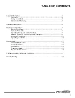
Page 3: ... 7 Design Conditions 7 Start Up Procedure 7 Operating Range and Control Settings 8 Digital Dry Guard DDG Controller Operation 9 Shutdown Procedure 10 Operating Conditions 10 Maintenance 11 Air Dryer Maintenance 10 Automatic Drains 10 Compressor 13 Expansion Valve 13 Hot Gas Bypass Valve 13 Refrigerated Air Dryer Service Check List 17 Troubleshooting 18 ...

Page 4: ...with damaged wiring or after the unit or air handling parts have been dropped or damaged in any manner Notify authorized service facility for examination repair or other adjustments 3 USE SUITABLE PARTS ACCESSORIES Do not use air pressurized accessories or parts in the air system not suitable for the maximum air pressure 4 RELEASE AIR PRESSURE SLOWLY Fast moving air will stir up dust and debris wh...

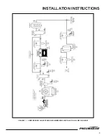
Page 5: ...INSTALLATION INSTRUCTIONS 4 FIGURE 1 COMPRESSED AIR SYSTEMS RECOMMENDED INSTALLATION FLOW DIAGRAM ...

Page 6: ...igh inlet temperature compressed air to the air dryer which will cause premature failures Aftercoolers must be followed by a separator and an automatic drain to remove the condensed moisture before the compressed air reaches the air dryer If the condensed water is not removed at the aftercooler separator drain it will reduce the cooling capacity of the air dryer Aftercoolers will condense approxim...

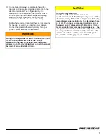
Page 7: ... meet the national NEC and local code requirements Check the voltage specified on the nameplate to the electrical power connecting to the dryer Electrical connections must be made by a qualified electrician CAUTION SCROLL COMPRESSOR Air dryers with a scroll compressor are unidirectional and to function properly they must be phased correctly To turn the compressor clockwise use a phase sequence ind...

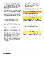
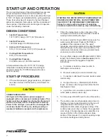
Page 8: ... DRYER WITHOUT ENERGIZING THE CRANKCASE HEATER WILL CAUSE PREMATURE FAILURE OF THE REFRIGERANT COMPRESSOR Failure to comply with procedure of energizing crankcase heater before start up may void warranty 2 Check the temperature on the crankcase of the compressor to make sure the crankcase heater is working before starting the dryer 3 For water cooled Air Dryers ADW make sure the water supply Minim...

Page 9: ...ure 25 to 33 PSIG Blue color range Refrigerant Discharge Pressure 75 to 170 PSIG Air cooled units 115 to 135 PSIG Water cooled units Refrigerant Low Pressure Switch Cut Out 20 PSIG Cut In 40 PSIG Refrigerant High Pressure Switch 250 PSIG Air cooled units 225 PSIG Water cooler units Fan Control Cut Out 110 PSIG Cut In 150 PSIG R 404a Refrigerant Suction Pressure 69 to 76 PSIG Orange color range Ref...

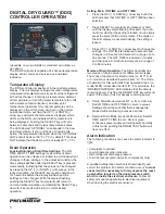
Page 10: ...ME and OFF TIME 1 Press the UP or DOWN arrow keys until the LED indicates that ON TIME or OFF TIME has been selected 2 Press SELECT momentarily if unlocked or hold until the display starts flashing if locked If you do not know whether the setting is locked or not simply press the select button momentarily If the digits on the LCD display do not start flashing the setting is locked 3 Press UP or DO...

Page 11: ... DOWN keys simultaneously This can not be done while a service due timer test is in progress SHUTDOWN PROCEDURE 1 Open the bypass valve to allow process flow to continue downstream Then close the outlet isolation valve on the dryer bypass piping 2 Close the inlet isolation valve on the dryer bypass piping At this time the dryer is isolated and can be depressurized ready for servicing 3 Turn the po...

Page 12: ...ified range after a few minutes of start up Suction pressure below the range will cause freeze up inside the air system increasing the pressure drop across the air dryer Suction pressure above the range will reduce the refrigeration cooling capacity 5 Check the pressure drop across the air dryer at full capacity flow If it is higher than specified value normally 5 PSI or less consult factory If pr...

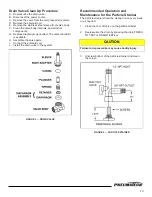
Page 13: ...vailable H Assemble the valve parts 12 I Connect the solenoid coil J Install the drain valve in the system FIGURE 3 DRAIN VALVE Recommended Operation and Maintenance for the Particle Strainer The particle strainer should be cleaned once every week or as needed 1 Close the shut off valve on the particle strainer 2 Depressurize the drain by pressing the drain PRESS TO TEST or DRAIN TEST key CAUTION ...

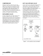
Page 14: ...se the suction pressure and counterclockwise to lower the suction pressure This adjustment should be made under a no load condition only When the adjustment is made turn one quarter of a turn at a time and wait 3 to 5 minutes between adjustments Once the adjustment is complete secure the adjusting stem with the locknut that is provided Careful adjustment of this valve is necessary for normal opera...

Page 15: ...14 FIGURE 6 FLOW DIAGRAM AD 750 to 1000 ...

Page 16: ...15 FIGURE 7 FLOW DIAGRAM AD 1200 to 2000 ...

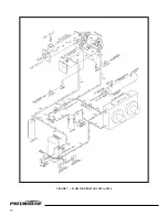
Page 17: ...FIGURE 8 FLOW DIAGRAM AD 2500 to 4000 16 ...

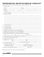
Page 18: ...______________________________________________________ 6 Air in pressure PSIG ___________________________________________________________________________ 7 Air out pressure PSIG __________________________________________________________________________ 8 Refrigerant suction pressure when unit is operating PSIG ______________________________________________ 9 Refrigerant suction pressure when unit ...

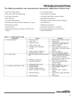
Page 19: ...ols open 5 Air switch open Dead end control 6 Frozen locked compressor 7 Wiring improper or loose 1 Close disconnect switch to start 2 Replace fuse 3 Turn switch off wait 15 minutes check for overload condition 4 Repair or replace 5 Check air pressure Adjust air and or switch If defective repair or replace 6 Repair or replace 7 Check wiring against diagram B Unit short cycles 1 Motor compressor ov...

Page 20: ...efective condenser pressure switch 6 Defective fan motor 7 Fan operating in wrong direction 8 Defective water regulating valve 1 Purge or vacuum and recharge 2 Check for reason repair 3 Blow clean with compressed air 4 Cool ambient relocate unit add ventilation 5 Repair or replace 6 Replace 7 Switch two wires at disconnect 8 Adjust repair or replace H Head pressure too low 1 Refrigerant shortage 2...

Page 21: ...ooler and or evaporator clogged 3 Incorrect piping 4 Air overload 5 Unit too small 6 Excess water in unit 7 Evaporator freeze up 8 Clogged air compressor intake filter 9 Dirty air system 1 Increase pressure 2 Back flush using mild detergent Figure 2 on Page 11 3 Increase line size and or correct piping as required 4 Reduce overload 5 Add another unit or replace with larger unit 6 Check drain repai...

Page 22: ...21 ...

Page 23: ...22 ...

Page 24: ...Pneumatech 4909 70th Avenue Kenosha WI 53144 Phone 262 658 4300 Fax 262 658 1945 www pneumatech com ...

Reviews: