background image

0000300349/230420/0 MDB-Diluter PRO 

4

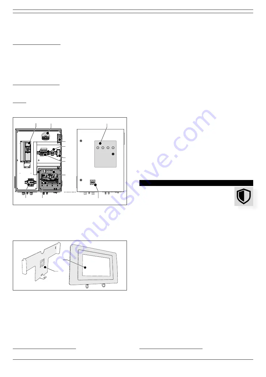
2.1.2  Control equipment

Panel

Fig. 2.1

High voltage compartment

A  VFD (frequency inverter)

B  Transformer

C  Cooling fan

D  Thermostat

E  Switch mode power supply

F  Circuit protectors

3

G  Main switch (interior parts)


Low voltage compartment

H  PC board

I  Manual controls

Outside

J  Status panel

K  Main switch (exterior parts)

Fig. 2.1 

A

B

G

I

F

D

C

H

J

K

E

Main components Panel 

HMI

Fig. 2.2

A  Touch screen

B  Mounting bracket

Fig. 2.2 

A

B

Main components HMI

Connection cables


- Panel 

 HMI cable


- motor cable


- PTC cable


- control cable (connected to the compressed air switch)

3.  CE (400V): circuit breakers | UL (480/600V): fuses

2.2 

Operation

2.2.1  MDB-Diluter

The air -that contains welding fume- is extracted through the 

air inlet module on top of the unit. The larger particles and any 

sparks are separated by a labyrinth-shaped

4

 spark arrester. 

Subsequently the air is cleaned by the eight filter cartridges. 

The air then passes the extraction fan and a duct silencer. The 

clean air is blown back into the workshop by the outlet unit 

with adjustable nozzles. 

The filter cartridges are cleaned individually from the inside 

out by compressed air pulses. This filter cleaning system is 

called the RamAir™ pulse amplifier. The dust and dirt particles 

are collected in the dustbin.

The fan speed is pressure controlled. 

Apart from air cleaning, the system optimises the present 

natural ventilation (draught) and/or forced ventilation (roof/

wall fans) system and equally distributes the present welding 

fume to reduce the background concentration of welding fume 

in the workshop.

2.2.2  ControlPro

ControlPro is an intelligent platform that controls the filter 

system as well as the connected extraction fan. It contains an 

extensive feature package to monitor and arrange the 

RamAir™ pulse amplifier (filter cleaning system), the required 

airflow and the corresponding fan speed. By means of the 

user-friendly HMI you can program all desired parameters. The 

HMI gives a clear insight into the system status and 

performance at all times. 

ControlPro allows for remote access via a network connection. 

SAFETY INSTRUCTIONS

General

The manufacturer does not accept any liability for 

damage to the product or personal injury caused by 

ignoring of the safety instructions in this manual, or 

by negligence during installation, use, maintenance, and repair 

of the product mentioned on the cover of this document and 

any corresponding accessories. Specific working conditions or 

used accessories may require additional safety instructions. 

Immediately contact your supplier if you detect a potential 

danger when using the product.

The user of the product is always fully responsible for 

observing the local safety instructions and regulations. 

Obey all applicable safety instructions and regulations.

User manual


- Everyone working on or with the product, must be familiar 

with the contents of this manual and must strictly obey the 

instructions therein. The management should instruct the 

personnel in accordance with the manual and obey all 

instructions and directions given. 


- Do not change the order of the steps to perform.


- Always keep the manual with the product.

Pictograms and instructions on the product (if 

present)


- The pictograms, warning and instructions attached to the 

product are part of the safety features. They must not be 

covered or removed and must be present and legible during 

the entire life of the product. 


- Immediately replace or repair damaged or illegible 

pictograms, warnings and instructions.

4.

  Refer to Fig. VI on page 28 for the airflow through the air inlet module 

Summary of Contents for MDB-DILUTER PRO

Page 1: ...www plymovent com Environmental diluter system Installation and user manual MDB DILUTER PRO EN...

Page 2: ...document and is therefore subject at any time to change or amendment and the right to change or amend is hereby expressly reserved The instructions in this publication only serve as a guideline for in...

Page 3: ...oduct The product consists of various components the identification plates of which contain the following data product name serial number supply voltage and frequency power consumption 1 2 General des...

Page 4: ...eptacle with dust cap ethernet 10 100 Mbit s RJ45 shielded with dust cap Display size type brightness colour resolution 7 resistive touch screen 300 cd m 262K 800 x 480 pixels Approvals certificates C...

Page 5: ...nnected extraction fan It contains an extensive feature package to monitor and arrange the RamAir pulse amplifier filter cleaning system the required airflow and the corresponding fan speed By means o...

Page 6: ...g the machine within the limits of its intended use also involves observing the instructions in the user manual Installation The installation of this product is exclusively reserved to authorised trai...

Page 7: ...2 Seal set MDB BM 4 3 Spare seal set MDB SealApplicator 6 E g heat gun cable stripping tool 7 The type of mounting material depends on the wall type 8 Number and type of cables depend on the selected...

Page 8: ...Air outlet module Fig 4 3 Temporary disassemble the back side of the frame to put the outlet module on the frame Fig 4 3 Air outlet module on frame Fig 4 4 Slightly lift the outlet module and put the...

Page 9: ...art with a long seal 1046 mm Try to avoid touching the sticky side with your fingers Make sure that you attach the seal in the centre of the frame edges and that the jigsaws fit together Peel approx 5...

Page 10: ...ably remove the remains of glue if any from the filter module e g with sticker remover Make sure that you do not damage the undamaged seals Apply a spare seal according to the above instructions ATTEN...

Page 11: ...seals 2 Put 4 positioning studs in the upper cage nuts of the first filter module corner positions 3 Spray SealApplicator lubricant on the seals 4 Put another filter module A within 60 seconds on the...

Page 12: ...compressed air switch B Connect the loose end of the pneumatic hose to the compressed air switch B via the T connector Install a compressed air regulator CAR KIT or similar C on the mounting frame Set...

Page 13: ...Attach the dustbin to the hopper with the quick connect clamp B Fig 4 26 A B C D Dustbin 4 9 1 Extraction fan Fig 4 27 Put the extraction fan on the fan frame Fig 4 27 A B Fan on frame In the standar...

Page 14: ...ermine the direction of the outlet unit and the airflow direction of the individual nozzles Depending on the specific circumstances it might be necessary to partly or fully close one or more nozzles F...

Page 15: ...filter compartment 3 Put the other hose through the connection Fig 4 33 1 2 3 Cable glands and pneumatic hoses Fig 4 34 Make sure to have approx 25 mm 1 in A B hose end Tighten all cable glands Fig 4...

Page 16: ...e gland M16 for the PTC cable C Cable gland M25 for the mains cord Low voltage compartment right bottom plate D Universal cable glands M16 4 E Push in fittings 3 for the pressure tubes20 Fig 4 38 A B...

Page 17: ...remain unused The PC board contains detachable screw terminal blocks connectors Table I on page 32 gives an overview of the necessary and optional cables22 that you need to install the system WARNING...

Page 18: ...Fasten the cable gland A B PE Fig 4 43 Mains cord 23 PE Protective Earth 4 12 2 Motor cable PTC cable To install the motor cable and PTC cable to the Panel do the following Fig 4 44 Put the motor cab...

Page 19: ...t 6 12 1 24V 2 IN 6 3 24V 4 IN 7 5 24V 6 IN 8 7 24V 8 IN 9 9 24V 10 IN 10 11 24V 12 IN 11 13 24V 14 IN 12 15 COM2 16 GND CAN Slave 1 2 CAN_H 3 CAN_L 4 GND 5 SHD 24V 1 2 A 3 B 4 GND 5 SHD RS485 VFD Fil...

Page 20: ...y closed Max connection 30 VDC 2 5 A per relay If desired connect Relay 1 and or Relay 2 to an external device You must select the specific event that you want to activate the relay s on the HMI refer...

Page 21: ...00 m h 885 CFM 9000 m h 5300 CFM 50 Hz For more detailed information refer to Fig X on page 31 Fig XI shows the horizontal throw per nozzle 5 3 1 PID setpoint of the fan pressure To determine and set...

Page 22: ...aintenance The system has been designed to function without problems for a long time with a minimum of maintenance In order to guarantee this some simple regular maintenance and cleaning activities ar...

Page 23: ...7 1 Turn off the main switch on the Panel to de energize the entire system Disconnect the compressed air supply Loosen the drain valve A to empty the compressed air tank Tighten the drain valve Fig 7...

Page 24: ...or both inspection covers Remove the inspection cover s Clean the inside of the module preferably with an industrial vacuum cleaner and a non agressive detergent Install the inspection cover s Fig 7...

Page 25: ...lack screen HMI does not function Loose connection Tighten the HMI cable to the CAN connector refer to Fig 4 41B C Loose or incorrectly connected cable Connect the HMI cable to the CAN HMI connector r...

Page 26: ...ctives Machine Directive 2006 42 EC LVD 2014 35 EU Low Voltage Directive Harmonised Standards EN IEC 60204 1 2006 Safety of machinery Electrical equipment of machines Part 1 General requirements EN IE...

Page 27: ...s MDB Diluter A B C D E F G H J K L M mm inch A 2095 82 5 B 897 35 3 C 1100 43 3 D 1312 51 7 E 1100 43 3 F 1124 44 3 G 3649 143 7 H 2072 81 6 I 803 31 6 J 1442 56 8 K 4945 194 7 M 1422 56 0 Fig II Dim...

Page 28: ...r PRO 27 ANNEX Fig III Air circulation Welding fume is mixed at source so optimum dilution Concentration of welding fume instead of dilution Example position of two systems Dilution filtration of a sp...

Page 29: ...ark arrester A Fig IV Overview of pneumatic and electric connections Ref Cable E Electric P Pneumatic For connection of To 1 Panel HMI E Panel HMI 5 Mains cord E Panel Mains 20 Control cable E Compres...

Page 30: ...00102666 Lid for filter cartridge CART MDB 0000102675 Filter cartridge holder MDB 0000103150 Magnetic valve 1 inch incl 24V DC coil and 3 m cable 0000104642 CART PTFE 15 Filter cartridge 0000110329 Se...

Page 31: ...0103139 Switch mode power supply 24V DC 2 5A 0000113558 Indicator light yellow 24V 0000113559 PCB main board ControlPro 0324000300 Indicator light white 24V 0324000310 Indicator light green 24V 032400...

Page 32: ...Correctie NR NR 0 NR 2 315 0 018 400 0 038 qv m3 h LT 10o vf m s VT m s VT LT m VT final velocity of throw Vf velocity at outlet of nozzle LT throw at VT qV air volume per nozzle Fig XI Horizontal thr...

Page 33: ...l alert input 8 Relay output 1 9 Relay output 2 20 Control cable compressed air switch H05VV F 2X0 75 22 Light tower H05VV F 7X0 5 23 Motor cable 190 CY 4X4 shielded 24 PTC cable 190 CY 2X0 75 shielde...

Page 34: ...www plymovent com 0000300349 230420 0 MDB Diluter PRO...

Reviews: