background image

Installation manual SR85

2

3

4

7

2

Figure 17

3-4

10

11

9

1

1

6

8

Summary of Contents for SR 85

Page 1: ...Installation Manual Bookletmaker SR 85 and Trimmer TR 85 January 2002 x17030 ...

Page 2: ...manual covers the installation of the Booklet maker SR 85 and the Trimmer TR 85 If you have any comments or remarks please contact us on one of the following numbers Email support oem plockmatic se Phone 46 8 602 50 41 1 800 648 57 73 Fax 46 8 722 9970 ...

Page 3: ...cking 2 2 Remove the Panels and Shelf 2 3 Power requirements 2 4 Preparing the printer 2 5 Interface 2 6 Wiring communication cable 2 7 Connectors communication cable 2 8 Adjustments 3 Installing the Trimmer 3 1 Unpacking 3 2 Power requirements 3 3 Attaching the Trimmer to the Bookletmaker Page 1 1 2 1 2 2 2 3 2 4 2 7 2 8 2 9 3 1 3 2 3 3 ...

Page 4: ...ements 1 1 Space requirements 1 Ensure that the minimum required floor space is available for an installation of the Bookletmaker SR 85 including the Trimmer TR 85 as shown in figure 1 Figure 1 1 1 505 mm 354 mm 873 mm 1 732 mm 400 mm 200 mm 555 mm ...

Page 5: ...stallation kit Box containing 1 EPROM 2 Exit arm catcher 3 Template 4 Communication cable 5 Powercord 6 Shift tray plate with four 6 x 5 5 mm counter screws 7 Exit tray plate with four 6 x 5 5 mm screws 8 Docking assembly for the printer with two screws 9 Tapping cable Box 1 EPROM 2 Exit arm Catcher 3 Template 4 Communication Cable 2 1 6 Shift tray plate 5 Powercord 8 Docking assembly for the prin...

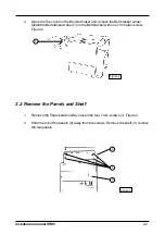
Page 6: ...e top of the panels 2 away from the screws Remove the shelf 3 remove the two panels 2 2 Remove the Panels and Shelf 4 Open the Top cover on the Booklet maker and remove the Belt stacker wheel Install the Belt stacker wheel 1 on the Belt stacker with one 7 mm allen screw Figure 2 Figure 2 1 2 2 Figure 3 2 3 1 ...

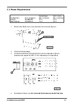
Page 7: ...es are tapped for 230V or 115V depending on configuration 4 Reinstall the Infeed cover Do not install the Panels and shelf at this time 1 Two 8 mm screws 2 Figure 4 Figure 5 2 Check wall outlet voltage 2 3 Power Requirements Bookletmaker With Trimmer Configuration Nom Voltage V Max Current A Max Current A Europe 220 230 240 0 5 A 2 0 A N S America 105 115 125 1 0 A 4 0 A ...

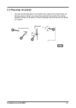
Page 8: ...ounting template 1 and hold it to the output on the printer finisher 2 Take the exit arm catcher 3 remove the adesive from the back of the catcher Install the catcher on the printer Lift up the exit paper arm and set onto the catcher 4 Figure 6 1 2 Figure 6 3 4 2 4 ...

Page 9: ...igure 7 5 Take the docking assembly 3 and install it with two positioning screws in the holes who were under the black plastic covers 2 Secure the docking assembly with the two nuts 4 Make sure you turn the nuts correct one diameter for the small hole and one diameter for the big hole There shall be no play in the Docking assembly if mounted correctly Figure 7 1 2 3 Small hole Big hole 2 5 4 Finis...

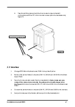
Page 10: ...the printer by removing four 5 5 mm screws figure 8 Figure 8 1 2 Figure 9 Four 5 5 mm screws 7 Take the printer exit tray 1 Take the exit tray plate 2 and install it with four 5 5 x 6 mm screws from the installation kit at the bottom of the exit tray figure 9 2 6 1 ...

Page 11: ...ors correctly the yellow wire should always be on top figure 12 Connect connectors CN115 CN120 and CN125 on the Main board PCB1 4 Connect the printer finisher connectors CN115 CN120 and CN125 to the harness 5 Secure the harness in the finisher with tie raps from the installation kit 2 7 Four 5 5 mm counter screws Figure 10 2 8 Take the shift tray plate 2 with the four counter holes and install it ...

Page 12: ...Installation manual SR85 Figure 11 2 6 Wiring communication cable 2 8 ...

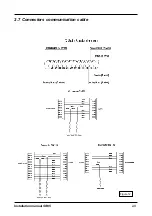
Page 13: ...Installation manual SR85 2 7 Connectors communication cable Figure 12 2 9 ...

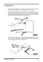
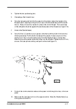
Page 14: ...g pins 5 with the caster tool The caster tool is located behind the front cover in the Bookletmaker The two black studs on the infeeder assembly should just have contact with the printer cover 6 figure 13 a 1 3 6 5 2 10 3 Adjust the distance between the front of the Bookletmaker infeeder and the front of the Printer panel 7 Adjust by moving the two positioning pins 5 with the castor tool The dista...

Page 15: ... at the infeeder 4 figure 13b 7 Undock the Bookletmaker 8 Take the front 1 and the rear 2 panels slide them with the bottom first onto the docking assembly Put the shelf 3 between the panels make sure you turn the shelf correct The cut out should be away from the Booklet maker not towards Slide the top of the panels under the screws on the infeeder Tighten the four 7 mm screws Take the printer exi...

Page 16: ...operation manual 4 2 16 Close the top cover press the yellow Run Adjustment button Take the book from the stacker and check the fold and the staples adjust if needed 17 Set up the Bookletmaker for A3 11 x 17 saddle stapling and folding according to the operation manual 4 2 Press the yellow Run Adjustment button on the Booklet maker 18 Send one A3 11 x 17 proof set from the Printer by pressing the ...

Page 17: ...ng 1 Exit guide bracket 2 Two 8 mm screws with 20 mm washers and two nuts to secure the trimmer to the Booklet maker 3 Plastic distance with one M5x25 screw 4 Tapping cable 1 Exit guide bracket 2 Screw with 20 mm washer 3 Plastic distance 3 1 4 Tapping cable Box 1 3 Ensure all of the packaging material is removed from the outside of the Trimmer TR85 3 Installing the Trimmer 2 x ...

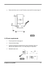
Page 18: ...mm screws figure 15 Figure 15 3 2 Power requirements 1 Power requirements see page 2 2 2 Check wall outlet voltage 3 Check the transformer 2 tapping for the correct configuration figure 16 Machines are tapped for 230V or 115V depending on configuration 4 Reinstall the rear cover Figure 16 2 ...

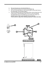
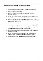
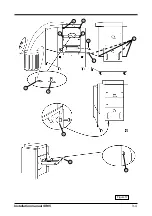
Page 19: ...17 Note Install it as high as possible 6 Move the Trimmer up to the Bookletmaker connect the communication cable 6 and the power cord 7 figure 17 Adjust the height on the Trimmer by turning the four nuts 8 figure 17 So that the two black positioning pins fits in the holes on the Trimmer Lower the Trimmer so that the Trimmer just hangs on the two positioning pins Make sure the cable not interferes ...

Page 20: ...Installation manual SR85 2 3 4 7 2 Figure 17 3 4 10 11 9 1 1 6 8 ...

Reviews:

Related manuals for SR 85