Installation manual SR85
6.
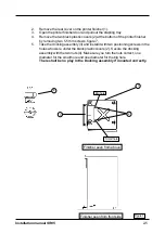
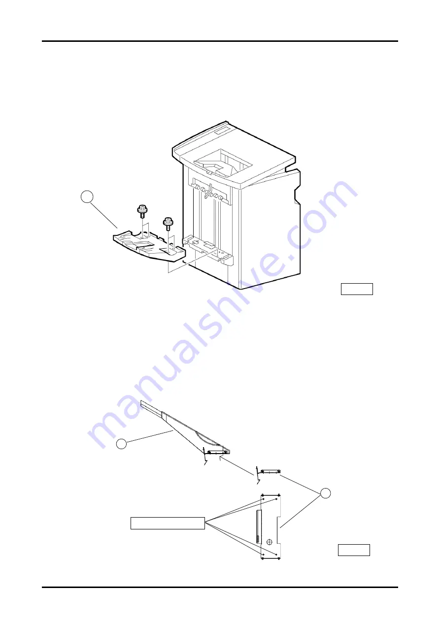
Remove the printer exit tray (1) from the printer by removing four 5.5 mm
screws, figure 8.
Figure 8
1
2
Figure 9
Four 5.5 mm screws
7.
Take the printer exit tray (1). Take the exit tray plate (2) and install it
with four 5.5 x 6 mm screws (from the installation kit) at the bottom of the exit
tray, figure 9.
2-6
1
Summary of Contents for SR 85
Page 1: ...Installation Manual Bookletmaker SR 85 and Trimmer TR 85 January 2002 x17030 ...
Page 12: ...Installation manual SR85 Figure 11 2 6 Wiring communication cable 2 8 ...
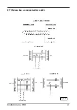
Page 13: ...Installation manual SR85 2 7 Connectors communication cable Figure 12 2 9 ...
Page 20: ...Installation manual SR85 2 3 4 7 2 Figure 17 3 4 10 11 9 1 1 6 8 ...

