background image

IMPORTANT NOTES: Read First

www.playcraftsystems.com

For Customer Service Call

800.333.8519 (U.S.A.) or 541.955.9199 (International)

TRANSFER STATION WITH HALF WALLS

INSTALLATION INSTRUCTIONS

Rev F

6/3/2020

1209-HW

Page 1 of 7

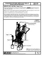
Figure 1.2

Figure 1.4

See Installation Manual 

Section 1309 Half Wall

for R5 & R3.5 only.

See Footing Detail

Figure 1.1

(A)

 Use liquid thread lock (such as Loctite

®

) with all threaded hardware. 

Important:

 Liquid thread lock (prior to 

curing) helps to eliminate the common problem of "thread seizure" in stainless steel hardware by serving as a 

lubricant during assembly.

(B)

 Do not pour concrete until the equipment is completely assembled, leveled and plumbed. Concrete must be 

allowed to cure completely before using the equipment (at least 72 hours).

(C)

 Refer to Installation Manual for 1309 Half Wall installation instructions.

(D)

 An appropriate energy absorbing safety surface is required under and around all playground equipment. 

Loose fill protective surfacing is shown only as an example for the purpose of this assembly instruction. Other 

surfacing material may vary in thickness and/or compression depths. See free publication - The Handbook for 

Public Playground Safety, Publication #325 at www.cpsc.gov for the surfacing appropriate for the fall height of 

the equipment or consult your surfacing supply representative.

FIGURE 1

Transfer Station

with Half Walls

NOTE

: R5 36" Deck Transfer Station with 

Half Walls shown. Other configurations will 

vary slightly, but does not affect assembly.

Figure 1.3

Summary of Contents for Transfer Station with Half Walls 1209-HW

Page 1: ...ed and plumbed Concrete must be allowed to cure completely before using the equipment at least 72 hours C Refer to Installation Manual for 1309 Half Wall installation instructions D An appropriate ene...

Page 2: ...16 427mm X See Table 3113 16 809mm 15 382mm 24 610mm Finish Grade Footing Detail Step 1 Refer to Footing Layout and mark footing hole locations Dig 4 12 footing holes and 1 12 x 24 oval footing hole...

Page 3: ...x 1 O D Washer 1 2 SAE Washer TRANSFER RAIL HALF WALL Figure 1 2 Figure 1 3 3 8 x 2 1 2 Button Head Bolt 3 8 x 1 O D Washer 3 8 Lock Nut TRANSFER RAIL ADA STEPS Step 2 Factory Assembled Drive Transfe...

Page 4: ...RANSFER DECK TRANSFER DECK SUPPORT 3 8 x 1 O D Washer 3 8 Lock Nut 3 8 x 1 O D Washer 3 8 x 1 1 4 Button Head Bolt FIGURE 4 3 8 Lock Nut 3 8 x 1 O D Washer TRANSFER RAIL 3 8 x 1 O D Washer 3 8 x 1 1 4...

Page 5: ...D Washer 3 8 Lock Nut FIGURE 5 Step 11 Attach Step Deck Legs to Step Deck as shown in Figure 6 See Note A Step 12 Place Step Deck into footing hole and attach Step Deck to Transfer Deck using Filler...

Page 6: ...lt Button Head 3 8 x 1 1 4 16 9103072 TR Bolt Button Head 3 8 x 1 1 2 8 9103112 TR Bolt Button Head 3 8 x 2 1 2 4 9333002 Washer Flat 3 8 x 1 O D x 100 thick 54 9345002 Washer Flat SAE 1 2 2 9413002 N...

Page 7: ...ed 1 660 O D 11 gauge steel support 1 029 O D 14 gauge steel rails and 1 4 thick steel mounting tab The Transfer Wall shall have a multi stage baked on powder coat finish TRANSFER LEG TOP Shall be pre...

Reviews: