background image

Lat/PA

3. Select the green check mark button.

13.1.2.3 Default kV / mA settings

For more information on setting the default kV / mA values, see section

"Exposure Values (1600)" on page 88.

13.1.3 Network Settings (1400)

About this task

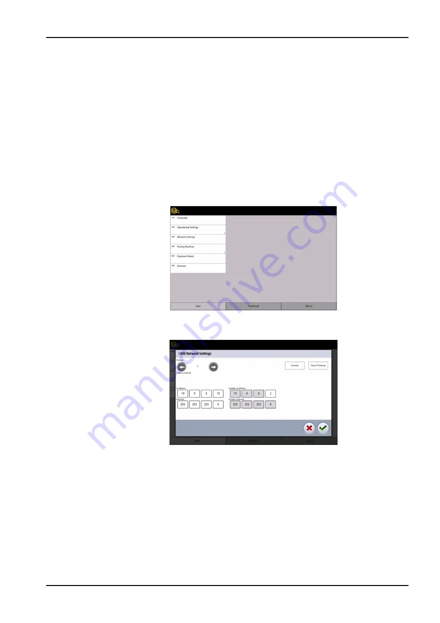
Follow these steps to view network settings.

Steps

1. Select User > 1400 Network Settings.

2. Select the network settings you wish to view.
3. Select the green check mark button.

NOTE

Only a service technician or local administrator may change the network

settings.

13  Settings

User's manual

Planmeca Viso 85

Summary of Contents for Viso

Page 1: ...Planmeca Viso user s manual EN 30005931 30005931...

Page 2: ...o the appropriate requirements such as IEC 60364 equipment is used according to the operating instructions Planmeca pursues a policy of continual product development Although every effort is made to p...

Page 3: ...unit 17 8 3 Patient supports 18 8 4 Exposure switch 19 8 5 Emergency stop button 19 8 6 Control panel 20 9 Before exposure 27 9 1 Preparing X ray system 27 9 1 1 Attaching patient supports 27 9 1 2 P...

Page 4: ...12 2 Running QA test 77 12 3 Post test process 81 13 Settings 82 13 1 User settings 82 13 1 1 Language 1100 82 13 1 2 Operational Settings 1300 83 13 1 3 Network Settings 1400 85 13 1 4 Testing Routin...

Page 5: ...puted tomography CBCT to produce three dimensional 3D images of the maxillofacial and ENT anatomies Two dimensional 2D images are produced with the tomosynthesis method panoramic imaging as well as co...

Page 6: ...2 1 Usage environment This X ray unit is intended to be used in a professional healthcare environment such as dental offices clinics and similar environments 1 Introduction 2 Planmeca Viso User s manu...

Page 7: ...ntation for the Planmeca Romexis program The Romexis package contains the following manuals User s Manual Technical Manual The original language of the manuals is English NOTE The User s Manuals are a...

Page 8: ...g smartphone hold the device steady over the QR code shown on the screen You are directed to Planmeca s product registration page Go to Planmeca s product registration page at https www planmeca com...

Page 9: ...ith EU 2017 745 Separate collection for electrical and electronic equipment according to Directive 2012 19 EU WEEE Consult electronic instructions for use Standard ISO 7000 1641 Refer to instruction m...

Page 10: ...Warning hot surface Standard ISO 7010 General warning Standard ISO 7010 4 Symbols 6 Planmeca Viso User s manual...

Page 11: ...ponsibility of the user to ensure that all local safety requirements are met CAUTION The patient positioning lights are laser lights Do not stare into the laser beam CAUTION If an exposure is interrup...

Page 12: ...t when you move the X ray unit down If something is in danger of becoming trapped release the height adjusting slider immediately to stop the movement Clear any obstruction before moving the X ray uni...

Page 13: ...ays first move the X ray unit down before you position the patient in the X ray unit NOTE Cone beam imaging should not be used for routine or screening examinations The imaging examinations must be ju...

Page 14: ...ditioning in the X ray room It is recommended to keep the room temperature between 20 C and 25 C at all times NOTE If exposures are taken in rapid succession the X ray tube may overheat and a cooling...

Page 15: ...nput signal output or other connectors has formed a system and is therefore responsible for the system to comply with the requirements of IEC 60601 1 If in doubt contact your service technician or loc...

Page 16: ...NOTE Portable mobile devices and other high frequency electromagnetic energy emitting devices used close to the X ray system may affect the system s performance Diagnostic information of the X ray im...

Page 17: ...n safety and or radiation safety for cone beam computed tomography devices Pediatric X ray Imaging http www fda gov Radiation EmittingProducts RadiationEmittingProductsandProcedures ucm298899 htm Medi...

Page 18: ...values for current exposure on page 43 2D panoramic exposure and Adjusting exposure values for current exposure on page 60 3D exposure The X ray unit provides the following specific testing informati...

Page 19: ...he X ray system off when it is not in active use 7 1 Switching X ray unit on The on off switch is located on the underside of the column top 7 2 Switching 3D reconstruction PC on The on off switch is...

Page 20: ...8 Main parts 8 1 General view of X ray system 1 X ray unit 2 3D reconstruction PC 3 Planmeca Romexis program 4 Ethernet switch 8 Main parts 16 Planmeca Viso User s manual...

Page 21: ...tient supports see section Patient supports on page 18 4 Patient handles 5 Touch screen see section Control panel on page 20 6 Moving column 7 Stationary column 8 Emergency stop button see section Eme...

Page 22: ...emple pads for children optional 4 Fastening straps optional 5 Support bars 6 Bite piece for panoramic exposures 7 Chin rest for panoramic exposures 8 Chin cup 9 Chin support for panoramic exposures 1...

Page 23: ...xposure a yellow radiation warning light illuminates on the exposure switch It indicates that the X ray unit is generating radiation 1 Exposure switch 2 Exposure button 8 5 Emergency stop button Press...

Page 24: ...ples NOTE The X ray unit can be upgraded with new programs and features Contact your dealer for further information NOTE Never allow patients to touch the screen when they are positioned in the X ray...

Page 25: ...display varies depending on which Viso model is in use The control panel pictures used in this manual are example images only and may not correspond to for example the Planmeca Viso G5 display Home bu...

Page 26: ...ram group button Accept button To accept a selection select the green check mark button Cancel button To cancel a selection and close a pop up window select the red cross button Home button To go to t...

Page 27: ...uch screen to move the X ray unit up or down Move the slider up to move the X ray unit up Move the slider down to move the X ray unit down The X ray unit moves slowly at first then faster About circle...

Page 28: ...on Checking DAP value DAP Dose Area Product The DAP value shown on the screen before you take an exposure is an estimate The actual DAP value is shown after the exposure Patient name When a patient is...

Page 29: ...you wish to practice or demonstrate the functions of the X ray unit without radiation and PC connection For more information see section Operational Settings 1300 on page 83 You see these symbols in...

Page 30: ...Closing virtual control panel Click on this cross if you need to close the virtual control panel on the computer screen 8 Main parts 26 Planmeca Viso User s manual...

Page 31: ...port base Steps 1 Press the trigger down and hold 2 Attach the adapter by sliding it into place in an upright position 3 Release the trigger 9 1 1 2 Removing adapter About this task Follow these instr...

Page 32: ...supports below for edentulous patients or for patients who are unable to bite 9 1 1 4 Attaching chin supports for 3D exposures Steps 1 Attach the support shown below to the adapter PNE_Chin3 eps 9 1 1...

Page 33: ...s 1 Release the locking lever 2 Pull out the head support 9 1 1 7 Attaching support bars About this task Follow these steps to attach the support bars to the patient support base Steps 1 Remove the pl...

Page 34: ...nnecting pins when inserting it into the patient support base to keep it steady Results The support bar is locked into place when you hear a clicking sound 9 1 1 8 Removing support bars Steps 1 Pull t...

Page 35: ...to adjust the head support to suit the size of the patient s head 3 You can use temple pads when you take exposures of children or patients with a small head Slide the temple pads onto the head suppo...

Page 36: ...ad as shown NOTE Be careful when you handle the straps Do not let the straps hit the patient in the eye or face NOTE Do not overstretch the straps The straps lose their elasticity if you pull them mor...

Page 37: ...spectacles hearing aids dentures hairpins and personal jewellery such as earrings necklaces and piercings as these can produce shadows or reflections in the image The patient should also remove any lo...

Page 38: ...maging and provides a wide exposure that shows the entire exposure area on a single plane Bitewing The Bitewing program produces bitewing images from premolar and molar areas including parts of maxill...

Page 39: ...rojections of the maxillofacial region as shown in the example below 1 Planmeca Viso G5 projection example results 2 Planmeca Viso G7 projection example results 10 2 Selecting imaging program Steps 1...

Page 40: ...ight corner of the imaging program option 10 3 Patient positioning Steps 1 Guide the patient to the X ray unit when you see this message NOTE The message does not display if the fast forward option is...

Page 41: ...en their back and neck and bite the bite piece The upper and lower incisors must be in the groove in the bite piece NOTE If you are using the chin support position the patient so that the chin touches...

Page 42: ...ith the midsagittal plane laser light The midsagittal plane laser light is shown in the middle of the patient s face 5 If you use the rear head support you can slide it up or down for optimal support...

Page 43: ...camera images of the patient s head on the control panel a front view and a side view The preset position of the panoramic image layer is shown with a blue area in both views Carefully position the pa...

Page 44: ...between the patient s second incisor and the canine The selected position is shown in the bottom right corner e g 1 mm Position the apices of the patient s upper central incisors within the image lay...

Page 45: ...Use the segmentation buttons to select the active exposure areas 10 2D exposure User s manual Planmeca Viso 41...

Page 46: ...re still correctly positioned Reposition them if necessary 10 4 Selecting patient size Steps 1 Use this button to select the patient size XS Child S Small adult M Medium sized adult L Large adult XL E...

Page 47: ...posure values are shown in the following table Factory presets for panoramic exposures Patient size kV value mAs value Child XS 64 110 Small adult S 66 125 Medium sized adult M 68 140 Large adult L 70...

Page 48: ...patient in the Planmeca Romexis program About this task Follow these steps to take a 2D Panoramic exposure Steps 1 Select the forward button Green lights flash on the control panel and exposure button...

Page 49: ...yellow radiation warning lights illuminate on the exposure switch and on the control panel Additionally you hear a radiation warning tone and see a radiation warning symbol on the control panel You ca...

Page 50: ...rom the X ray unit 7 The image is shown on the computer screen Results The image is shown on the computer screen 10 6 2 2D View exposure Before you begin Make sure that you have selected the correct p...

Page 51: ...rol panel and exposure button when the X ray system is getting ready for an exposure You see this message NOTE Move to a protected area The green lights stop flashing and stay on continuously when the...

Page 52: ...tch and on the control panel Additionally you hear a radiation warning tone and see a radiation warning symbol on the control panel You can follow the imaging process on the virtual control panel NOTE...

Page 53: ...ake the exposure with the same settings Select this button if you want to go to the home screen 7 Release the patient from the head support 8 Guide the patient away from the X ray unit Results The ima...

Page 54: ...11 3D exposure 11 1 3D dental programs 3D dental programs include 3D programs 3D ENT programs Special programs 3D programs 3D ENT programs 11 3D exposure 50 Planmeca Viso User s manual...

Page 55: ...size Volume range Note Tooth 50 50 mm 30 30 mm 60 60 mm 5 mm steps 75 m voxel possible only with volumes smaller than 70 x 70 mm TMJ 50 50 mm 30 30 mm 60 60 mm 5 mm steps Teeth 100 100 mm 70 30 mm 120...

Page 56: ...ize Volume range Note Tooth 50 50 mm 30 30 mm 60 60 mm 5 mm steps 75 m voxel possible only with volumes smaller than 70 x 70 mm TMJ 50 50 mm 30 30 mm 60 60 mm 5 mm steps Teeth 90 90 mm 70 30 mm 90 90...

Page 57: ...TE When taking a 3D image for jaw tracking with the Planmeca 4D Jaw Motion system select the Face program See Planmeca Viso 4D Jaw Motion user s manual for more information Results The sensor moves to...

Page 58: ...ient can sit or stand during the exposure NOTE We recommend that you image patients with poor health in a sitting position 2 Use the height adjusting slider on the touch screen to move the X ray unit...

Page 59: ...ou use the rear head support you can slide the rear head support up or down for optimal support of the patient s head 6 If you use the top head support You can adjust the head support by turning the a...

Page 60: ...patient s left or right side About this task Follow these instructions to select the patient s left or right side NOTE This function is not available for the Skull program The sensor contains digital...

Page 61: ...to the selected side and an image of that side is shown on the screen You see this message Patient s left side selected Patient s right side selected 11 5 Selecting patient size Steps 1 Use the butto...

Page 62: ...images of the patient s head on the control panel a front view and a side view The preset position and size of the image volume are shown with a blue area in both views You can use either or both view...

Page 63: ...her adjusted in that direction The selected volume size diameter and height is shown in the bottom right corner of the screen Viso_UM_M096 eps NOTE With Tooth program you can alternatively use the but...

Page 64: ...OTE The available options depend on the selected program NOTE The exposure values will automatically change according to the selected patient size image resolution and ULD setting The preset exposure...

Page 65: ...2 120 20 Factory presets for Sinus Nose and Airways programs Child XS Small adult S Medium sized adult M Large adult L Extra large adult XL Voxel size kV mAs kV mAs kV mAs kV mAs kV mAs 600 90 14 90 1...

Page 66: ...nt correction button 4 if you wish to minimise the effects of movements on the image The Planmeca CALM function is an algorithm that detects patient movement during exposure and then compensates for t...

Page 67: ...utomatically saved in the Planmeca Romexis program under 2D images CBCT tab Make sure that you have selected the correct patient in the Planmeca Romexis program NOTE The scout view function can yield...

Page 68: ...s flash on the control panel and exposure button when the X ray system is getting ready for an exposure You see this message NOTE Move to a protected area The green lights stop flashing and stay on co...

Page 69: ...Additionally you hear a radiation warning tone and see a radiation warning symbol on the control panel 7 If needed you can now fine adjust the volume position and size To fine adjust the volume positi...

Page 70: ...and move the ball to enlarge or reduce the volume size The ball turns red when you reach the limit value i e when the volume diameter or height cannot be further adjusted in that direction The select...

Page 71: ...ibed above Make new fine adjustments until the image volume is in the correct place 11 11 Taking 3D exposure Before you begin Make sure that you have selected the correct patient in the Planmeca Romex...

Page 72: ...e button when the X ray system is getting ready for an exposure You see this message NOTE Move to a protected area The green lights stop flashing and stay on continuously when the X ray system is read...

Page 73: ...trol panel If you take a skull exposure with two image volumes the lower volume 1 2 is imaged first and the upper volume 2 2 last The C arm is automatically moved up between the volumes You can follow...

Page 74: ...elected the second phase of the exposure i e the image of the selected exposure area is taken NOTE In this phase no radiation is used The C arm moves around the patient s head and the image is generat...

Page 75: ...ime depends on the selected settings For example if you selected the ULD Ultra Low Dose button you have to wait longer before the image appears If you took a skull exposure with two image volumes you...

Page 76: ...e screen until the Frankfort line and the patient s eye are correctly positioned as shown in the image below NOTE You can move the Frankfort line and eye markers using a finger touch screen or the mou...

Page 77: ...NOTE Do not release the exposure button before the end of the exposure s NOTE Maintain audio and visual contact with the patient and X ray unit during exposure If the C arm stops moving during exposur...

Page 78: ...to retake the exposure with the same settings Select this button if you want to go to the home screen 7 Remove the fastening straps if used Release the patient from the head support 8 Guide the patie...

Page 79: ...Results The image is shown on the computer screen 11 3D exposure User s manual Planmeca Viso 75...

Page 80: ...compatibility CAUTION Only qualified service technicians may perform QA testing using the full Planmeca Device Tool installation If performing the QA test using the Device Tool QA program read this s...

Page 81: ...the 3D QA phantom to the patient support base 2 Switch on the X ray unit 3 Start the Device Tool QA in the clinic computer 4 From the Device Tool launcher select the VISO left option 12 3D quality con...

Page 82: ...ton to continue Planmeca QA tests consists of the following test QA 3D C Arm Center QA 3D Middle Arm Center QA 3D Middle Arm Offset 8 Select the QA 3D C Arm Center from the calibration task list if no...

Page 83: ...and click the Start button 11 Press the exposure button to take the exposure CAUTION Protect yourself from radiation The following image view appears 12 Select the QA 3D Middle Arm Offset from the ca...

Page 84: ...report page you can select which of the QA tests you want to include in the report 15 Once your selections are ready click Create Report The report opens in a new browser window For more information o...

Page 85: ...ith Pass example below QA test passes After successful QA test remove the 3D QA phantom from the patient support table QA test fails If the QA test fails the unit is not correctly adjusted and calibra...

Page 86: ...only examples Select the settings symbol on the main screen to enter the settings menu Settings that can be entered by the user User About Settings that can be entered by service personnel only passwo...

Page 87: ...e you wish to use 3 Select the green check mark button 13 1 2 Operational Settings 1300 13 1 2 1 Mode 1310 Steps 1 Select User 1300 Operational Settings 1310 Mode 2 Select the mode you wish to use 131...

Page 88: ...diation and PC connection 1312 Normal Mode 3 Select the green check mark button 13 1 2 2 Scout Settings 1320 Steps 1 Select User 1300 Operational Settings 1320 Scout Settings 2 Select the default scou...

Page 89: ...1600 on page 88 13 1 3 Network Settings 1400 About this task Follow these steps to view network settings Steps 1 Select User 1400 Network Settings 2 Select the network settings you wish to view 3 Sel...

Page 90: ...cted area 5 Press and hold down the exposure button for the duration of the exposure The C arm does not move when you take a test exposure 6 Select the green check mark button 13 1 4 2 3D test exposur...

Page 91: ...n a tube head seasoning process This is necessary if the X ray unit has not been used for a week or more and or if you receive error message E332 Severe arcing across X ray tube 2 Select the START but...

Page 92: ...Exposure Values 1600 Steps 1 Go to 1600 Exposure Values to check the default kV and mA settings for 3D or Panoramic imaging The values can be adjusted as follows 5 kV increments for 3D 2 kV increments...

Page 93: ...e a program licence Steps 1 Select User 1700 Licences 2 Select the licences you wish to activate 3 Enter the licence code that you have received for this licence on this X ray unit 4 Select the green...

Page 94: ...ponent Information Show Component Information to view the set up or current software versions of the X ray unit To view software build information Select About 4100 Component Information Show Detailed...

Page 95: ...ect About 4200 Archive 4210 Error History to view a list of the error messages that have been generated by the X ray unit The errors are shown in chronological order with the latest error message on t...

Page 96: ...0 Archive 4220 Exposure Statistics to view statistical data about the X ray unit 13 2 3 Product Registration 4300 For more information on product registration see section Product registration on page...

Page 97: ...Contact your service technician if you need to replace the exposure switch H105 Emergency stop button The emergency stop button has been activated All movements of the X ray unit are blocked and no r...

Page 98: ...e C arm cannot be moved higher Clear any obstruction before continuing H150 Height movement was stopped because the patient support base cannot be moved lower Clear any obstruction before continuing H...

Page 99: ...nsmission Exposure was interrupted Contact your service technician for help H186 No IP address defined for 3D sensor H187 Problem during image data transmission Exposure was interrupted Contact your s...

Page 100: ...an error message e g E201 appears on the control panel An error message indicates that the X ray unit has a problem that needs to be solved before further exposures can be taken The X ray unit will n...

Page 101: ...acturers NOTE Follow the instructions provided by the manufacturer of the cleaning agent disinfectant and autoclave NOTE FOR SPRAYS LIQUIDS AND FOAMS Do not apply sprays liquids or foams directly on t...

Page 102: ...Patient supports 16 Cleaning and disinfection 98 Planmeca Viso User s manual...

Page 103: ...Patient handles and touch screen NOTE These parts can be autoclaved at 134 C 273 F They can be autoclaved at least up to 100 times 16 Cleaning and disinfection User s manual Planmeca Viso 99...

Page 104: ...Wipe the other surfaces regularly using a Planmeca approved surface disinfectant Use a Planmeca approved cleaning agent for cleaning stains and dirt if needed 16 Cleaning and disinfection 100 Planmeca...

Page 105: ...arantee patient and user safety and ensure consistent image quality The annual maintenance service includes inspection of the following X ray unit adjustments and quality control checks Data security...

Page 106: ...ponents containing hazardous materials must be disposed of in accordance with waste legislation and instructions issued by the local environmental authorities The following parts contain hazardous was...

Page 107: ...mm Al 0 2 mm 0 5 mm Cu Pan SmartPan ProCeph Total 2 5 mm Al Tube housing front cover quality equivalent filtration not included in the specified total filtration 0 3 mm Al 70 kV HVL 2 6 mm Al Anode v...

Page 108: ...nt 8 17 A Input power Stand by 150 VA Exposure 1800 W Line harmonics Cos better than 0 9 Max permissible apparent impedance of supply mains 0 5 ohm 100 VAC Max continuous heat dissipation 250 W Intern...

Page 109: ...mm 11 89 x 9 80 in 3D Flat panel pixel size Planmeca Viso G5 127 m Planmeca Viso G7 139 m Flat panel active surface Planmeca Viso G5 157 5 x 157 5 mm 6 20 x 6 20 in Planmeca Viso G7 299 7 x 246 3 mm 1...

Page 110: ......

Page 111: ......

Page 112: ...Planmeca Oy Asentajankatu 6 00880 Helsinki Finland tel 358 20 7795 500 fax 358 20 7795 555 sales planmeca com www planmeca com...

Reviews: