background image

Using Discrete IR Codes

Planar UltraRes User Manual

113

Supported UltraRes IR Commands

Remote Control 

Button Name

Address

Data

NEC Data From Remote

On

1785

1

0x06F901FE

HDMI 1 

1785

2

0x06F902FD

DisplayPort 1

1785

3

0x06F903FC

HDMI 2 

1785

6

0x06F906F9

DisplayPort 2

1785

7

0x06F907F8

Off

1785

9

0x06F909F6

HDMI 3

1785

10

0x06F90AF5

DisplayPort 3

1785

11

0x06F90BF4

Single Input

1785

13

0x06F90DF2

HMDI 4

1785

14

0x06F90EF1

DisplayPort 4

1785

15

0x06F90FF0

Multiple Inputs

1785

17

0x06F911EE

Menu

1785

21

0x06F915EA

Previous

1785

22

0x06F916E9

Enter

1785

23

0x06F917E8

Up

1785

26

0x06F91AE5

Left

1785

29

0x06F91DE2

Right

1785

31

0x06F91FE0

Down

1785

24

0x06F918E7

Summary of Contents for UltraRes

Page 1: ...Planar UltraRes User Manual...

Page 2: ...nection with the furnishing performance or use of this material Warranty and Service Plans Planar warranty and service plans will help you maximize your investment by providing great support display u...

Page 3: ...in Standby Mode 17 Input Setup 18 Supported Formats for Multiple Inputs 18 Installing a Planar UltraRes Display 19 Before You Begin 19 Tools Equipment List 19 Other Things You May Need 19 Plan Your I...

Page 4: ...utputs 51 NVIDIA Graphics Card Setup for Single Output 53 NVIDIA Graphics Card Setup for Quadrant Output 59 Installing the UltraRes Control Software 61 Installing USB Drivers 64 Using the UltraRes Con...

Page 5: ...er On Off 90 Remote Monitoring Source Setup 91 Remote Monitoring Advanced Setup 92 Remote Monitoring Custom Commands Setup 93 Remote Monitoring Admin Setup 93 Remote Monitoring Network Setup 94 Remote...

Page 6: ...creen PQLabs MultiTouch Platform Content 115 Touchscreen Information 115 Calibration 115 Utility 115 Options 115 Uninstalling the MultiTouch Driver 115 Specifications 117 Signal Compatibility 120 Ultr...

Page 7: ...138 98 UltraRes Touch Side Views 139 98 UltraRes Touch Rear View 140 Troubleshooting During Installation 141 UltraRes LED Codes 141 Error Codes in the UltraRes Control Software 142 Symptoms Possible...

Page 8: ...s required in leading control rooms collaboration rooms and digital branding installations Some of the features of the UltraRes display are Ultra HD 3840 x 2160 resolution Outstanding picture quality...

Page 9: ...s accessories specified by the manufacturer 11 Unplug all Planar UltraRes displays during lightning storms or when unused for long periods of time 12 You must follow all National Electrical Code regul...

Page 10: ...Planar UltraRes User Manual 10 17 The polarizer is a thin sheet of film laminated to the outside layer of glass on the LCD screen Take care when handling items near the screen...

Page 11: ...European Disposal Information...

Page 12: ...ccur when a static image is displayed continuously for extended periods of time An electrical charge differential may build up between the electrodes of the liquid crystal which causes a negative colo...

Page 13: ...sts it is up to the installer to ensure that module placement is changed thermal shielding is provided and or additional ventilation is provided to keep the display within its nominal operating parame...

Page 14: ...DisplayPort There are four main modes of operation for the UltraRes Display Single 4K inputs 24 25 30Hz Single 4K inputs 50 60Hz HDMI 4 2 0 Four headed input 4K 60Hz Two headed input 4k 60Hz Using fou...

Page 15: ...5 Using the Remote Control The UltraRes remote control can be used for a variety of functions including turning the display on and off and assigning individual inputs Turn display on off Selectsingle...

Page 16: ...ng the On Off buttons on the remote control See Using the Remote Control on page 15 for more information Using the Power On Power Off buttons in the UltraRes Control software tool See Using the UltraR...

Page 17: ...not the display is on but in standby mode look for the small Standby LED If it is off you will not see the LED If it is on but in Standby mode you will see a blue LED As the display starts the LED bli...

Page 18: ...urces on page 42 and Setting up for Single Input Sources on page 40 Supported Formats for Multiple Inputs The following formats are supported for multiple inputs Quadrants or Single Inputs 4K 24 25 30...

Page 19: ...er Things You May Need LCD screen cleaner or LCD wipes available at most electronics stores Three strong people to lift display into place A mechanical lift device Plan Your Installation You should ha...

Page 20: ...ave application specific 3D settings that must be set up See the specific program s user manual for instructions on application specific 3D setup Note Consult the specific graphics card s user manual...

Page 21: ...ion of AMD card setup is given in AMD Graphics Card Setup for Quadrant Outputs on page 51 1 Right click on the desktop and select Catalyst Control Center 2 Select AMD FirePro then select 3D Applicatio...

Page 22: ...VIDIA Control Panel 2 Under 3D Settings select Manage 3D Settings 3 Select the Program Settings tab 4 In section 1 select the program for which its 3D capabilities will be used If the program is not l...

Page 23: ...User Manual 23 Recommended PCs In order to use 4K video it is crucial that you have a high powered PC We also recommend using a single 4K output whenever possible Doing so eliminates the requirement...

Page 24: ...ption Number Picture LCD module One per box 1 LCD mounts optional If ordered this will be inside a separate box inside the LCD box Note If you do not use Planar s mounts you need to ensure the mounts...

Page 25: ...ts to the display when Planar mounts are purchased 1 M4 x 8 Panhead screws 84 only Used to mount the kickstand bracket 4 Lift block assembly 98 only Used as attachment points for lift assist machines...

Page 26: ...r cord Power cord 1 IR sensor Used to receive signals from the remote control 1 Double sided tape Used to help in mounting the IR sensor module 2 USB drive Contains the User Manual and setup software...

Page 27: ...nd Checking Accessories Planar UltraRes User Manual 27 Carrying Strap For lifting and carrying the display using two people 2 3D glasses 98 only For viewing 3D content 4 Part Description Number Includ...

Page 28: ...be installed on a flat surface If you ordered the optional wall mounts use the supplied UltraRes mounting template for the center point of the display as well as for top and bottom bracket installati...

Page 29: ...he correct hardware needed to support the display mounted to that structure Caution If the unit being installed is fitted with a touch input device it is important that the touch frame is not used to...

Page 30: ...3 Use the provided template to determine the center points of the wall mounts The V notches are labeled L for a landscape display or P for a portrait display Use the appropriate V notch to align with...

Page 31: ...You may wish to screw the template in place to make the next steps easier Note If you are installing a landscape display and the template is too long you can break the template at the notch labeled P...

Page 32: ...ts for a landscape installation 9 Tighten the screw into the mount 10 Use a level to make sure the mount is level 11 Then install additional screws as needed Note Screws installed near the mount hooks...

Page 33: ...n a Wall Planar UltraRes User Manual 33 13 84 only Install the kickstand bracket to the back of the display using four M4 x 8 Panhead screws Landscape holes for kickstand bracket installation Portrait...

Page 34: ...aRes Display on a Wall Planar UltraRes User Manual 34 14 Using three physically capable people carefully hang the back of the display onto the top wall mount bracket using the square brackets on the b...

Page 35: ...As an alternative for the 98 model you can use the lift blocks along with a lift assist mechanism to lift the panel into place For details refer to Using the Lift Blocks 98 only on page 36 15 On the b...

Page 36: ...he lift blocks to the back of the panel using the provided M8 x 35 pan head screws 2 Securely attach your lift mechanism to the eyehooks a Spreader bar attachment A spreader bar allows for a small lif...

Page 37: ...nd the support lines should not be less than 45 degrees This means that the attachment point must be at least 485 mm 19 1 in above the top of the panel 3 Lift the panel into place 4 Detach the upper h...

Page 38: ...splay in service mode 1 Loosen the captive locking screws on both sides of the bottom mount and let the brackets hang down freely 2 Pull the display out and then swing out the kickstand s to hold it i...

Page 39: ...e supplied AC power cord connect one end to a grounded outlet and the other to the AC power input next to the I O panel the bottom of the UltraRes display Connecting the Wired IR Module In order for t...

Page 40: ...25 30 50 60Hz 1080i 50 60Hz 720p 50 60Hz 3 Two headed input 960x2160 60Hz 1920x2160 60Hz using inputs 1 3 or 2 4 Setting up for Single Input Sources Connect from a single headed source to the display...

Page 41: ...Connecting Sources Planar UltraRes User Manual 41 Selecting a single source with the remote Press the button that has the 4K source connected Select Single...

Page 42: ...Control Software on page 61 and Using the UltraRes Control Software on page 65 Setting up for Multiple Input Sources Multiple input sources can be managed efficiently with UltraRes MediaPlex Multiple...

Page 43: ...anual 43 Selecting multiple sources with the remote Press the buttons for each source that you want to display For example to display HDMI 1 DisplayPort 2 HDMI 3 and DisplayPort 4 press the HDMI 1 DP...

Page 44: ...of 4K sources PCs with NVIDIA graphics cards such as NVIDIA Quadro K5000 PCs with AMD graphics cards such as AMD Radeon 7970 HDMI 4K sources like Blu ray such as Sony BDP S790 Note Apple has provided...

Page 45: ...tup area select the input that will be used for Input 1 Note You can t use both input connectors at the same time on one input 3 Do the same for each of the other input sources Select the first source...

Page 46: ...mation The Planar UltraRes defaults to an EDID that indicates it is 1080p 60Hz display Many graphics cards can t handle 4K timing so you must setup the EDIDs to indicate 4K timing You must do this for...

Page 47: ...eferred Screen Resolution Setup If your source is 4K 24Hz you will use that one This is the best one for film content For all others use 4K 30Hz 1 On the Desktop of your computer right click and choos...

Page 48: ...Connecting Sources Planar UltraRes User Manual 48 5 After this is done click Keep Changes...

Page 49: ...2160 is already listed If it is currently selected you are finished If it is in the list but not selected select it and click Apply If it is not in the list then you have to set it up as a custom reso...

Page 50: ...raphics cards For single outputs 24Hz or 30Hz the graphics cards must be set up for correct timing output For quadrant outputs 4x 1080p or 2x 1920x2160 the quadrants must be seamed together to create...

Page 51: ...raRes User Manual 51 AMD Graphics Card Setup for Quadrant Outputs 1 Right click on the desktop and select Catalyst Control Center 2 Select AMD Eyefinity Multi Display then select Create Eyefinity Disp...

Page 52: ...nar UltraRes User Manual 52 3 Each quadrant will be shown separately in blue Select each quadrant in the CCC window to indicate its location CCC will arrange the quadrants to show one unified display...

Page 53: ...ick on the desktop and select NVIDIA CONTROL PANEL Now go to Help System Information Check the Driver version field It should be 311 15 or later We recommend using the latest version 340 66 as of 12 S...

Page 54: ...4 2 Select Change Resolution on the left 3 Select Planar Systems Inc Planar UltraRes in the list of displays Note If using 4K 60Hz 4 2 0 under Resolution select 3840 x 2160 in the PC list and click Ap...

Page 55: ...tup for Single Output Planar UltraRes User Manual 55 4 Click the Customize button at the bottom Check Enable resolutions not exposed by the display 5 Click Create Custom Resolution 6 Set the parameter...

Page 56: ...in the Standard dropdown list choose CVT Reduced Blanking or Automatic Parameter 4K 24Hz output timing 4K 30Hz output timing Horiz pixels 3840 Vertical lines 2160 Refresh rate 24Hz 30Hz Scan type Prog...

Page 57: ...setup is similar but with the following differences Horizontal pixels 1920 Vertical lines 2160 Refresh rate 60 Hz Standard CVT Reduced Blanking or Automatic 7 Click the Test button 8 Click Yes to save...

Page 58: ...NVIDIA Graphics Card Setup for Single Output Planar UltraRes User Manual 58 10 Close the NVIDIA Control Panel window...

Page 59: ...lanar UltraRes User Manual 59 NVIDIA Graphics Card Setup for Quadrant Output 1 Right click on the desktop and select NVIDIA Control Panel 2 Select Set up Premium Mosaic and check Enable Premium Mosaic...

Page 60: ...d Setup for Quadrant Output Planar UltraRes User Manual 60 3 Check the box for all four of the displays shown 4 Under Configuration select 2x2 5 Arrange the display numbers to match the diagram shown...

Page 61: ...e UltraRes Control software is used as your primary tool for display setup Use the following instructions to install the UltraRes Control software 1 Save the UltraRes Control msi program to your compu...

Page 62: ...choice 5 If you want to see how much space is on your hard drive click the Disk Cost button to review storage capacity 6 Do one of the following If you want other users to have access to the UltraRes...

Page 63: ...Planar UltraRes User Manual 63 8 Click Next to continue 9 As the installation is occurring you will see the status bar for up to a couple of minutes...

Page 64: ...and to the UltraRes display You only need to complete a few steps to finish the installation process 1 Plug one end of the USB cable into your computer and the other into the UltraRes display 2 Windo...

Page 65: ...similar to the following Notice that until you connect the inputs to the display the Status at the top of the window will show Disconnected 1 Connect from the PC on which the software is installed to...

Page 66: ...ts that are already connected One of the following will occur If an input is detected the following window appears with information already filled in If no input is auto detected you will see a window...

Page 67: ...of the window will show Connected Note that all tabs are now accessible and can now be changed if needed Setting Up Sources This information is covered earlier in the manual Please see Setting up for...

Page 68: ...en a low power setting which saves energy or a fast startup mode that keeps the AC power supplies running Each option is described below Low Power Powers off every component and board possible which h...

Page 69: ...ash Screen Under the SETTINGS tab you can select whether or not to display a Splash Screen Choose LANDSCAPE or PORTRAIT to display the splash screen for five seconds or OFF The splash screen is only d...

Page 70: ...a PLUGE This typically shows white and black chips and several gray chips in between Adjust the Brightness control until the black chip disappears into the background The darkest Gray chip should be...

Page 71: ...n incandescent light Native uses the color temperature of the display itself with no adjustment Gamma Gamma is a curve of the brightness and contrast that used correctly can improve the separation and...

Page 72: ...an EDID with 4K 30Hz as the default timing 1080p Preferred Selects an EDID with 1080p 60Hz as the default timing 960x2160 Preferred Selects an EDID with 960x2160 60Hz as the default timing 1920x2160...

Page 73: ...sets the color space matrix to that defined in ITU R BT 709 RGB PC uses RGB color space and sets black at 0 0 0 RGB and white at 255 255 255 RGB assuming an 8 bit image RGB Video uses RGB color space...

Page 74: ...nces in the dark areas of the image A good way to do this is to use a test pattern consisting mostly of dark gray areas such as a 30 IRE window pattern If the gray areas contain traces of red green or...

Page 75: ...a brighter display move the slider towards a higher number If you want to conserve power and increase backlight life move the slider towards a lower number Turning Local Dimming On or Off Local Dimmi...

Page 76: ...6 Changing Frame Delay With some quadrant sources the top and bottom halves of display can show frame tearing at a delay of one frame per second If you see frame tearing use the Top Half Frame Display...

Page 77: ...Firmware Planar UltraRes User Manual 77 Upgrading Firmware Upgrading firmware can only be done through the UltraRes Control software using a USB connection 1 Select the FILE menu bar and then UPGRADE...

Page 78: ...te The upgrade can be initiated from ON or standby mode 3 The upgrade process will take about 40 minutes Be sure you are prepared for this amount of time before you initiate the upgrade process 4 The...

Page 79: ...ual 79 Error Log To see the last 50 errors that have occurred select the Error Log tab in the UltraRes Control software as shown below For a complete list of the error codes see Error Codes in the Ult...

Page 80: ...ool and connect to the display 3 Select the Info tab The IP address is shown towards the bottom of the tab 4 One of the following will occur If the IP address is 192 168 12 12 then DHCP failed Use the...

Page 81: ...s shows anything else then DHCP succeeded To confirm the connection open a Windows command prompt and use the ping command with the IP address shown in UltraRes Control Note If you cannot confirm a co...

Page 82: ...f 192 168 12 12 24 1 The PC must be configured to an IP address on the 192 168 12 network We recommend 192 168 12 100 2 Assuming the operating system is Windows 7 you can follow these instructions to...

Page 83: ...Manual 83 4 Open Network and Sharing Center 5 Click Change adapter settings in the left side pane 6 Right click on the local area connection that corresponds to the network interface that is connecte...

Page 84: ...Static IP Network Setup Planar UltraRes User Manual 84 7 Select Internet Protocol Version 4 TCP IPv4 and then click the Properties button...

Page 85: ...2 168 12 100 for the IP address 255 255 255 0 for the Subnet mask and 192 168 12 1 for the Default gateway Click OK to dismiss the IPv4 Properties window Then click Close to dismiss the Local Area Con...

Page 86: ...browser It is used primarily for monitoring reporting and some control for example manually powering the displays on and off Remote Monitoring Home Launch a web browser If you are using DHCP enter in...

Page 87: ...ng Custom Commands Planar UltraRes User Manual 87 Remote Monitoring Custom Commands The Custom Commands page enables you to execute custom serial commands You define these commands on the Custom Comma...

Page 88: ...it Status The Unit Status page shows a list of the different system settings for the display including power signal format and which sources are connected with which inputs It also shows all current f...

Page 89: ...Display Control Planar UltraRes User Manual 89 Remote Monitoring Display Control The Display Control page contains three sub pages Power On Off Source Setup and Advanced Setup These are described in t...

Page 90: ...ntrol AC power through Planar UltraRes Remote Monitoring This section has four options for which you can schedule an automatic power on off The options are No automatic power on off Same daily schedul...

Page 91: ...g Source Setup The Source Setup page allows you to perform the same tasks that you can using the Remote Monitoring software Select single or multiple input mode Select an input source for each input i...

Page 92: ...ws you to perform many of the same tasks that you can on the UltraRes Monitoring software program This includes selecting the power mode that works best for your display either low power or fast start...

Page 93: ...Setup The Custom Commands Setup page enables you to create custom commands that you can execute from the Custom Commands page Remote Monitoring Admin Setup The Admin Setup page contains four sub pages...

Page 94: ...ain name box 3 Do one of the following If you will use DHCP go to step 4 If you will not use DHCP go to step 5 4 Under the DHCP section select the Yes use DHCP radio button a Change the default DHCP t...

Page 95: ...new name in the upper left corner of the page Remote Monitoring Date and Time Use this page to change date and time information as needed 1 Set the date and time manually in the box under the Manual D...

Page 96: ...U S locales that observe daylight saving time must enter start and end dates in this section For example EST5EDT M3 2 0 M11 1 0 is correct for U S Eastern time zone as of 2007 Remote Monitoring Acces...

Page 97: ...at you do not interrupt the load process once it begins 3 If you want to reset ALL settings to the factory default click Reset ALL to Factory Default This includes network settings date and time etc a...

Page 98: ...for user requests that have been made using the IR remote control and the on screen menus In some situations this polling can have a noticeable performance impact If you want to disable this polling s...

Page 99: ...there are other methods of controlling the UltraRes externally Using a serial RS232 link to send ASCII commands and to receive responses to those commands Using discrete infrared IR codes to program a...

Page 100: ...ith RS232 commands Plus you can send inquiries to the displays and find out the current settings and values RS232 connections are made with standard straight through cables Connecting the RS232 Cable...

Page 101: ...Manual 101 Setting Up Single Inputs Using RS232 Commands You can set up single inputs using RS232 commands As is typical with using RS232 commands you can pull up a basic program such as Tera Term to...

Page 102: ...or shall assume the data is not valid display data and ignore it www indicates the command code This field is case insensitive i e PWR pwr and PwR should all be treated as PWR x is the destination par...

Page 103: ...used 0 Command successfully processed 1 Unknown command code 2 Invalid operator 3 Destination parameter not supported 4 Setting not available 5 Setting value not available 6 Setting value not supporte...

Page 104: ...query when unit is powered on Command PWR CR Response 0 PWR 1 CR Example Set power to 0 off Command PWR 0 CR Response 0 PWR 0 CR Example Increment brightness from 24 to 25 Command BRT CR Response 0 BR...

Page 105: ...Timer APT R W No 1 60 No No Value is in minutes Backlight BKL R W No 1 15 No No Brightness BRT R W No 0 100 No No Blank Screen Blue BSB R W No 0 255 No No Blank Screen Green BSG R W No 0 255 No No Bl...

Page 106: ...o N A N A Yes No Response contains 50 hex digits representing the second 25 entries in the error log Error Code ERR R No 0 TBD No No 0 None 1 AC Power Supply 1 Failure 2 AC Power Supply 2 Failure 3 AC...

Page 107: ...A N A Yes No Information FPGA 4 Version IF4 R No N A N A Yes No Information Firmware Version IFV R No N A N A Yes No Input Mode INM R W No 0 2 No No 0 Single Input 2 Multiple Inputs Input Source INS R...

Page 108: ...t 1 87 DisplayPort 2 88 DisplayPort 3 89 DisplayPort 4 90 Single Input 91 Multiple Inputs 92 Previous Local Dimming LDM R W No 0 1 No No 0 Off 1 On Model Name MDL R No N A N A Yes No Multiple Input 1...

Page 109: ...W No N A N A Yes No String format aabbccddeeff where aa is the Input Source value in hex bb is the Input Mode value in hex cc is the Multiple Input 1 setting in hex dd is the Multiple Input 2 setting...

Page 110: ...is any internal system or communication error and normal return values are zero or positive integers Object Name Description Value plnrModel Model name string UltraRes plnrSWPart Part number string fo...

Page 111: ...Note Ensure that the Enable ASCII command service UDP port 57 box is checked on the Access Control page of the Remote Monitor software see Remote Monitoring Access Control on page 96 Notice the follow...

Page 112: ...a modulated pulse of 9 ms followed by a non modulated pulse of 4 5 ms 16 address bits The default address is 1785 0x06F9 binary 00000110 11111001 16 data bits eight 8 bits for the command followed by...

Page 113: ...2 1785 6 0x06F906F9 DisplayPort 2 1785 7 0x06F907F8 Off 1785 9 0x06F909F6 HDMI 3 1785 10 0x06F90AF5 DisplayPort 3 1785 11 0x06F90BF4 Single Input 1785 13 0x06F90DF2 HMDI 4 1785 14 0x06F90EF1 DisplayPo...

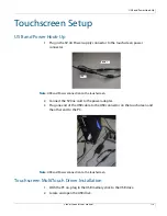
Page 114: ...d Power connection to the touchscreen 2 Connect the 5V line cord to the power adapter 3 Plug one end of the USB cable to the USB connector on the touchscreen and the other end to the PC Note USB and P...

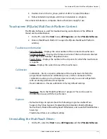
Page 115: ...dropdown menu Touch Points Displays the number of touch points for which the touchscreen is capable Status Displays the current status of the touchscreen Calibration Calibration Starts a 4 point cali...

Page 116: ...Uninstalling the MultiTouch Driver Planar UltraRes User Manual 116 2 Click on the MultiTouch Driver 3 Select the Uninstall option...

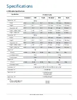
Page 117: ...mm 2202 5mm 2210 0mm Height 49 5 49 5 49 8 1257 5mm 1257 5mm 1265 0mm Diagonal overall 99 9 99 9 100 3 2536mm 2536mm 2546mm Depth without mount 3 60 3 60 3 95 91 3mm 91 3mm 100 4mm Depth with mount 3...

Page 118: ...abled 84 LX 84 MX 98 1100 1 1000 1 900 1 1600 1 1400 1 1300 1 Uniformity 84 98 70 75 Viewing Angle 2D content 3D content left right 3D content up down 89 in all directions 89 in all directions 26 comb...

Page 119: ...Altitude barometric pressure 3000m Humidity operating non operating 85 R H 90 R H non condensing non condensing Low line voltage range 100 120V High line voltage range 200 240V Line frequency range 49...

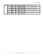
Page 120: ...l parameters doubled 3840x2160 24 52 438 209 75 VESA CVT R 3840x2160 30 65 688 262 75 VESA CVT R EDTV 480p 60 31 469 27 ITU R BT 1358 CEA 861 E Format 17 18 576p 50 31 25 27 SMPTE 125M CEA 861 E Forma...

Page 121: ...2009 HDMI 1 4b VIC 1 3840x2160 25 56 250 297 000 SMPTE ST 2036 1 2009 HDMI 1 4b VIC 2 3840x2160 30 67 500 297 000 SMPTE ST 2036 1 2009 HDMI 1 4b VIC 3 3840x2160 4 2 0 50 56 250 297 000 SMPTE ST 2036...

Page 122: ...Signal Compatibility Planar UltraRes User Manual 122...

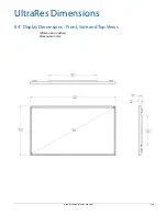
Page 123: ...Planar UltraRes User Manual 123 UltraRes Dimensions 84 Display Dimensions Front Side and Top Views dimension in inches dimension in mm...

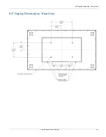
Page 124: ...84 Display Dimensions Rear View Planar UltraRes User Manual 124 84 Display Dimensions Rear View...

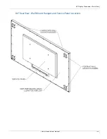
Page 125: ...84 Display Dimensions Rear View Planar UltraRes User Manual 125 84 Rear View Wall Mount Hangers and Service Panel Locations...

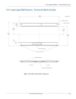
Page 126: ...84 Landscape Wall Mounts Front and Bottom Views Planar UltraRes User Manual 126 84 Landscape Wall Mounts Front and Bottom Views Note Shown from the bottom of the panel...

Page 127: ...84 Landscape Wall Mounts Sides Views Planar UltraRes User Manual 127 84 Landscape Wall Mounts Sides Views...

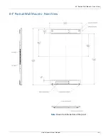
Page 128: ...84 Portrait Wall Mounts Front View Planar UltraRes User Manual 128 84 Portrait Wall Mounts Front View Note Shown from the bottom of the panel...

Page 129: ...84 Portrait Wall Mounts Sides Views Planar UltraRes User Manual 129 84 Portrait Wall Mounts Sides Views...

Page 130: ...84 UltraRes Touch Front Top and Bottom Views Planar UltraRes User Manual 130 84 UltraRes Touch Front Top and Bottom Views...

Page 131: ...84 UltraRes Touch Side Views Planar UltraRes User Manual 131 84 UltraRes Touch Side Views 8...

Page 132: ...84 UltraRes Touch Rear View Planar UltraRes User Manual 132 84 UltraRes Touch Rear View...

Page 133: ...98 Display Dimensions Front Side and Top Views Planar UltraRes User Manual 133 98 Display Dimensions Front Side and Top Views dimension in inches dimension in mm...

Page 134: ...98 Display Dimensions Rear View Planar UltraRes User Manual 134 98 Display Dimensions Rear View...

Page 135: ...98 Display Dimensions Rear View Planar UltraRes User Manual 135 98 Rear View Wall Mount Hangers and Service Panel Locations...

Page 136: ...98 Landscape Wall Mounts Front and Bottom Views Planar UltraRes User Manual 136 98 Landscape Wall Mounts Front and Bottom Views Note Shown from the bottom of the panel...

Page 137: ...98 Landscape Wall Mounts Sides Views Planar UltraRes User Manual 137 98 Landscape Wall Mounts Sides Views...

Page 138: ...98 UltraRes Touch Front Top and Bottom Views Planar UltraRes User Manual 138 98 UltraRes Touch Front Top and Bottom Views...

Page 139: ...98 UltraRes Touch Side Views Planar UltraRes User Manual 139 98 UltraRes Touch Side Views...

Page 140: ...98 UltraRes Touch Rear View Planar UltraRes User Manual 140 98 UltraRes Touch Rear View...

Page 141: ...in this section please contact Planar s Technical Support team for assistance UltraRes LED Codes The LED on the UltraRes display will show different things depending on the state of the display System...

Page 142: ...ailure One of the two AC power supplies is not working properly The backlight will be dimmed to a maximum setting of 10 which is necessary in order to reduce power consumption Solution Replace the fai...

Page 143: ...ot start up correctly There are two possible causes one of the FPGAs has corrupt code or is damaged Solution First check the FPGA status LEDs on the main board If one is not blinking that FPGA didn t...

Page 144: ...4K output Solution Make sure that your graphics card can support a 4K output See Supported Graphics Cards on page 20 for a list of the current graphics cards that Planar supports for the UltraRes dis...

Page 145: ...other quadrant inputs For example if you are using HDMI 1 4 and the current Input Source is HDMI 1 change it to HDMI 2 Possible Cause The connector overmold is too large which can cause the pins not t...

Page 146: ...won t be able to power back on later if Standby Mode is set to Low Power Solution Make sure Standby Mode is set to Fast Startup in the UltraRes Control software See Standby Mode on page 68 for more in...

Page 147: ...nuals Downloading Additional Documentation and Firmware Some of the other documents for the UltraRes 4K professional display which are or will be available on www planar com Downloading Utility Softwa...

Page 148: ...red by this Directive is maintained at the corporate headquarters of Planar Systems Inc 1195 NW Compton Drive Beaverton OR 97006 Note This equipment has been tested and found to comply with the limits...

Page 149: ...error 142 codes LED 141 color gamut LCD module 118 color temperature 71 communicating via RS232 commands 100 compatible video sources 120 conformity information 148 connecting RS232 cable 100 UltraRe...

Page 150: ...ews 127 137 LCD installation 28 mounts 24 optical specifications 118 wipes 19 LCD module 24 contents in box 24 dimensions 117 operating temperature 119 orientation 117 screen brightness 118 specificat...

Page 151: ...control 89 home 86 network setup 94 power on off 90 rebooting the system 98 software setup 97 source setup 91 Unit Status 88 resolution of LCD module 118 RS232 command formats 102 command response ex...

Page 152: ...ror codes 79 installing software 61 installing USB drivers 64 powering on off display 16 setting up sources 67 troubleshooting via error codes 142 UltraRes display basics 14 compatible signals 120 ins...

Reviews: