background image

Output pulse length

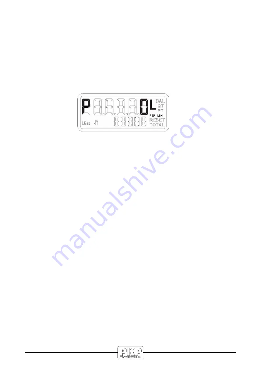
Indicated by a “P” on the left hand side of the display, this screen allows the
selection of the low duration of the output pulse.

“0” for zero milliseconds (pulse output is disabled)

“2” for 2 milliseconds

“10” for 10 milliseconds

“20” for 20 milliseconds

“40” for 40 milliseconds

“100” for 100 milliseconds

To advance to the next programming screen, hold the TOTAL button.

Output pulse length screen

About Output Pulse Length: The pulse rate duration should take into account the "Pulse
Rate Out" and maximum meter flow rate, to prevent an output pulse duration greater than
the required time between pulses. The Output Pulse Length should be set to less than the
value of “t.”

Per the equation: 

Maximum meter flow rate (in GPM or l/m)

t = ----------------------------------------------------------------- x 1000 

60 X output pulse rate

where t = the required pulse rate in milliseconds.

The output pulse rate = the programmed parameter (default = 1.00 PPL/PPG)

The maximum meter flow rate = the maximum flow rate of the meter for the application. 

DOZ03 / DOZ05 / DOZ07  Instruction manual  02/2021

page  25

Summary of Contents for DOZ03

Page 1: ...Instruction Manual DOZ03 DOZ05 DOZ07 Oval gear flowmeter PKP Prozessmesstechnik GmbH Borsigstraße 24 D 65205 Wiesbaden Nordenstadt Tel 49 0 6122 7055 0 Fax 49 0 6122 7055 50 Email info pkp de www pkp de ...

Page 2: ... work safety instructions in this manual as well as the safety accident prevention and environmental protection regulations generally valid for the work area must be observed The liability of the manufacturer expires in the event of damage due to improper use non observance of this operating manual use of insufficiently qualified personnel and unauthorized modification of the device Proper Usage T...

Page 3: ...ection to intrinsically safe electric circuit simple electrical equip ments must be operated intrinsically safe with a suitable barrier according to EN 60079 11 Equipotential bonding has to be ensured upon the pipe system Meters with plastic housing do not clean the meters with a dry cloth as this would cause electrostatic charge The fluid conductivity must be higher than 1000 pico Siemens meter t...

Page 4: ...r use with this equipment Use only fluids and solvents that are compatible with the equipment Read all fluid and solvent manufacturer s warnings Tighten all fluid connections before operating this equipment Do NOT stop or deflect leaks with hands body gloves or rags Do NOT dispense towards any person or any part of the body Do NOT place hands or fingers over the end of or into the dispense valve C...

Page 5: ...tative for specific information per your specific application Figure 1 Meter installation Turn off any associated pumps to reduce line pressure and slowly fill the line and meter with fluid before restarting pumps Doing so reduces the possibility of meter damage caused by errant air pressures in the line and meter Make sure all pipe conforms to the same pressure output rating as the pump Make sure...

Page 6: ... the outlet port Each rotation of the gears displaces a specific volume of fluid As the gears rotate a magnet on each end of the gear pass a reed switch in the top mounted register s circuit board The reed switches send pulses to the microprocessor in the register to change the LED display segments Pressure loss diagrams DOZ03 DOZ05 DOZ07 Instruction manual 02 2021 page 6 ...

Page 7: ...for DOZ07 only DOZ03 DOZ05 DOZ07 Instruction manual 02 2021 page 7 ...

Page 8: ...DOZ03 DOZ05 DOZ07 Instruction manual 02 2021 page 8 ...

Page 9: ...r The register is protected from normal wear and tear by a robust shockproof housing Operation The magnets integrated in oval gear counters send pulses to the register The register is in sleep mode until pulses arrive The pulses are generated by the liquid flowing through the meter The register shows the current flow rate the subtotal and the total The resettable totaliser has a 6 digit display wi...

Page 10: ... Rating Power rating 10 W Switching voltage 100 V DC or peak AC Switching current 500 mA DC or peak AC Wiring Grey Reedswitch White Reedswitch Green Hall effect pulse output Pulses per liter PPL Meter size meas range code measuring range pulses L 1 8 06 0 017 0 83 l min appr 4400 1 4 08A 0 04 1 67 l min appr 2170 1 4 08B 0 25 8 33 l min appr 390 Note Pulses per liter are shown unit specifically on...

Page 11: ...s gallon DOZ05 1 2 ca 100 ca 378 5 DOZ05 3 4 ca 66 ca 249 8 DOZ05 1 ca 66 ca 249 8 DOZ07 1 ca 43 ca 162 8 DOZ07 1 1 2 ca 17 ca 64 4 DOZ07 2 ca 9 ca 34 1 DOZ07 3 ca 3 ca 11 4 Note Pulses per liter are shown unit specifically on the calibration certificate supplied and on the type plate DOZ03 DOZ05 DOZ07 Instruction manual 02 2021 page 11 green white ...

Page 12: ... mA Outputs Analogue 4 to 20 mA output in loop powered configuration external load of 50 ohms to 250 ohms flow rate is linear scaled between 4 mA minimum and 20 mA maximum set points flow rates below programmed minimum read 4 mA Pulse output with internal pull up resistor 10 KΩ optional open collector output with output jumper removal pulse output is scalable in pulses per liter or pulses per gall...

Page 13: ...15 nF a cable length of 10m is considered Effective internal inductance Li 35 µH a cable length of 10m is considered Switch state indicator LED yellow Ambient temperature 25 to 70 C 13 to 158 F Cable length 2 meters PVC Core cross section 0 34 mm Material Stainless steel 1 4404 316L Protection class IP66 IP67 Marking Namur CE 0102 Ex II2G Ex ib IIC T6 Gb DOZ03 DOZ05 DOZ07 Instruction manual 02 202...

Page 14: ...4 ca 66 ca 249 8 DOZ05 1 ca 66 ca 249 8 DOZ07 1 ca 43 ca 162 8 DOZ07 1 1 2 ca 17 ca 64 4 DOZ07 2 ca 9 ca 34 1 DOZ07 3 ca 3 ca 11 4 Note Pulses per liter are shown unit specifically on the calibration certificate supplied and on the type plate DOZ03 DOZ05 DOZ07 Instruction manual 02 2021 page 14 white ...

Page 15: ...ctive internal inductivity Ci 12 nF Effective internal inductance Li 0 µH Cable length 3 meters Material Stainless steel 1 4404 316L Protection class IP66 IP67 Marking USA Intrinsically safe Class I II III Division 1 GROUP ABCDEFG T6 to T5 Class I Zone 0 AEx ia IIC T6 to T5 Canada Intrinsically safe Class I Division 1 GROUP ABCD T6 to T5 Class I Zone 0 Ex ia IIC T6 to T5 ATEX Ex II 1G Ex ia IIC T6...

Page 16: ... 3 4 ca 66 ca 249 8 DOZ05 1 ca 66 ca 249 8 DOZ07 1 ca 43 ca 162 8 DOZ07 1 1 2 ca 17 ca 64 4 DOZ07 2 ca 9 ca 34 1 DOZ07 3 ca 3 ca 11 4 Note Pulses per liter are shown unit specifically on the calibration certificate supplied and on the type plate DOZ03 DOZ05 DOZ07 Instruction manual 02 2021 page 16 ...

Page 17: ...s and release the RESET button The bottom row of indicators display the resettable totalizer with five digits or the five least significant digits of the non resettable totalizer RESET and TOTAL is indicated when the resettable total is displayed in the five digit lower row Only TOTAL is indicated when the non resettable total is displayed To toggle between the non resettable totalizer and the res...

Page 18: ... 10 of its total capacity and should be changed Normal battery life is five years Checksum To display the firmware checksum press and hold the RESET button for three seconds To return to normal display release the RESET button Display scale factor To display the scale factor At the same time press and hold the TOTAL and RESET buttons for two seconds to display the programmed scale factor To return...

Page 19: ...en press the RESET button three times the time lag between pressing both buttons six times must be within two seconds Changing the unit of measure and scale factor Unit of measure 1 Press and release the RESET button to change the unit of measure L GAL QT PT 2 Press and release the TOTAL button to select desired the unit of measure theselected unit of measure will flash 3 When the appropriate unit...

Page 20: ...w the user to advance to the next screen Changing the meter pulse rate The meter pulse rate screen is indicated by the I on the top row on the left side is the number of pulses per unit of measure as detected by the register The pulse rate varies according to the type of attached meter The bottom row consists of the 5 digit integer value of the meter pulse rate whereas the top row consists of the ...

Page 21: ...e options I for an inline to flow orientation and P for a perpendicular to flow orientation or O for Remote versions and for the oval gear meters DOZ03 DOZ05 DOZ07 2 When finished adjusting the register orientation press and hold the TOTAL button for one second to advance to the Default Display section DOZ03 DOZ05 DOZ07 Instruction manual 02 2021 page 21 Flow direction Inline Perpendicular ...

Page 22: ...lashing on the display press the RESET button to select either totalizer or flow rate 2 Upon completion of this setting the programming of the industrial standard register and the industrial dual pulse output is complete Exiting programming mode To exit the programing mode On any screen press and hold the both the TOTAL and RESET buttons The screen will revert back to the programmed scale factor a...

Page 23: ... linearisation is completed press and hold the TOTAL button for one second to advance to the next linearisation point Linearisation point 9 of 9 Number 9 at the left hand side of the display shows the 9th linearisation point The sample shows a flow rate of 250 0 liter per minute and a deviation of the flow meter of 0 15 To correct this error 0 15 needs to be set as correction NOTE Minimum 3 linear...

Page 24: ... the next screen To advance to the next programming screen hold the TOTAL button for one second Analogue minimum flow rate screen Analogue maximum flow rate Indicated by a H on the left hand side of the display this screen allows the setting of the flow rate that corresponds to the 20mA output NOTE The maximum flow rate value must be greater than the minimum flow rate value Minimum 0 0 LPM GPM Max...

Page 25: ...out Output Pulse Length The pulse rate duration should take into account the Pulse Rate Out and maximum meter flow rate to prevent an output pulse duration greater than the required time between pulses The Output Pulse Length should be set to less than the value of t Per the equation Maximum meter flow rate in GPM or l m t x 1000 60 X output pulse rate where t the required pulse rate in millisecon...

Page 26: ...gnal sequence of pulse output Signal sequence of pulse output This parameter can be changed for the signal inversion of the pulse output io 1 default setting no signal inversion at no flow condition the pulse output signal is 1 high 24V for example io 0 the output is inverted by the software at no flow condition the pulse output signal is 0 low 0V Cleaning Before cleaning switch off the appliance ...

Page 27: ...nsor or reed contact and output as a pulse The output frequency of these pulses is directly proportional to the flow rate Optionally the device can be combined with an on site display which also offers an analogue and pulse output In addition to the connection size in combination with the measuring range various material combinations sealing materials and process connections ensure a wide range of...

Page 28: ...7 l min 08B 1 4 15 500 l h 0 25 8 33 l min Material housing rotor Pmax Tmax AE aluminium stainless steel 55 bar 120 C EE st steel st steel 100 bar 120 C PE PVDF stainless steel 16 bar 60 C AR aluminium PPS 55 bar 80 C ER stainless steel PPS 100 bar 80 C PR PVDF PPS 16 bar 60 C Output signal RH potential free reed contact and Hall sensor 2 pulse outputs 3 m cable Process connection 1 BSP female thr...

Reviews: