D200-62-00 3 I56-932-07
1. Wire the plug-in screw terminal block per Figure 3 and
plug the terminal block into the detector.
2. Align the arrows on the detector with the arrows on the
mounting bracket.
3. Turn the detector clockwise in the mounting bracket un-
til it clicks into place.
4. After all detectors have been installed, apply power to
the control unit or initiating device circuits.
NOTE: This detector has a feature that will signal an
alarm at the control panel if wiring polarity is
incorrect.
5. Test the detector as described in
TESTING
.
6. Reset the detector at the system control panel.
7. Notify the proper authorities the system is in operation.
CAUTION
Dust covers are an effective way to limit the entry of dust
into smoke detector sensing chambers. However, they may
not completely prevent airborne dust particles from en-
tering the detector. Therefore, System Sensor recommends
the removal of detectors before beginning construction or
other dust producing activity. Be sure to remove dust covers
from any sensors that were left in place during construction
as part of returning the system to service.
Testing
NOTE:
Before testing, notify the proper authorities that the
smoke detector system is undergoing maintenance
and will be temporarily out of service. Disable the
zone or system undergoing maintenance to prevent
unwanted alarms.
Detectors must be tested after installation and following
TAMPER SLOT
(DEPRESS TAB TO
REMOVE DETECTOR)
TAMPER RESISTANT TAB
(CUT OFF SMALL TAB TO
ACTIVATE TAMPER-RESIST
FEATURE)
ALIGNMENT
ARROWS
LED
TEST MODULE
SOCKET
RECESSED TEST
SWITCH
PUSH RECESSED
SWITCH WITH A
0.18
″
MAX. DIAMETER TOOL
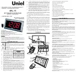
Figure 3. 2112/24D(A) and 2112/24TD(A) smoke detector mounting bracket:
A78-2333-01
Figure 4. Top and side views showing position of test switch:
periodic maintenance. Test the 2112/24D(A) as follows:
A. Test Switch
1. A recessed test switch is located on the detector hous-
ing (See Figure 4).
2. Press and hold the recessed test switch with a 0.18
inch maximum diameter tool such as an allen wrench
or small screwdriver.
3. The detector’s LED should light within 5 seconds.
B. Test Module (System Sensor Model No. MOD400R)
The MOD400R test module can be used with a DMM
or analog voltmeter to check the detector sensitivity as
described in the test module’s manual.
C. Smoke Entry Test
Hold a smoldering punk stick or cotton wick at the side
of the detector and gently blow smoke through the de-
tector until the unit alarms.
D. Direct Heat Method (Model 2112/24TD(A) only – Hair
dryer of 1000-1500 watts)
Direct the heat toward either of the side thermistors.
Hold the heat source about 12 inches from the detector
in order to avoid damage to the plastic. The detector will
reset only after it has had sufficient time to cool and the
power source has been momentarily interrupted.
Both smoke and heat detection testing are recommended
for verifying system protection capability.
A detector that fails to activate with any of the above tests
should first be cleaned as outlined in
MAINTENANCE
. If
the detector still fails to activate, return it for repair.
Notify the proper authorities the system is back in
operation.
A78-2564-00
firealarmresources.com