background image

INSTALLATION & OPERATIONAL SSHLV MANUAL 


22 

L20-407 rev.5 (06/19)


WARNING 

The power supply must be disconnected before cleaning and servicing this appliance! 

WARNING 

The contents of the crumb catch and/or filter pan of any filter system must be emptied into a fireproof 
container at the end of the frying operation each day.  Some food particles can spontaneously combust 
into flames if left soaking in certain oil/shortening materials. 


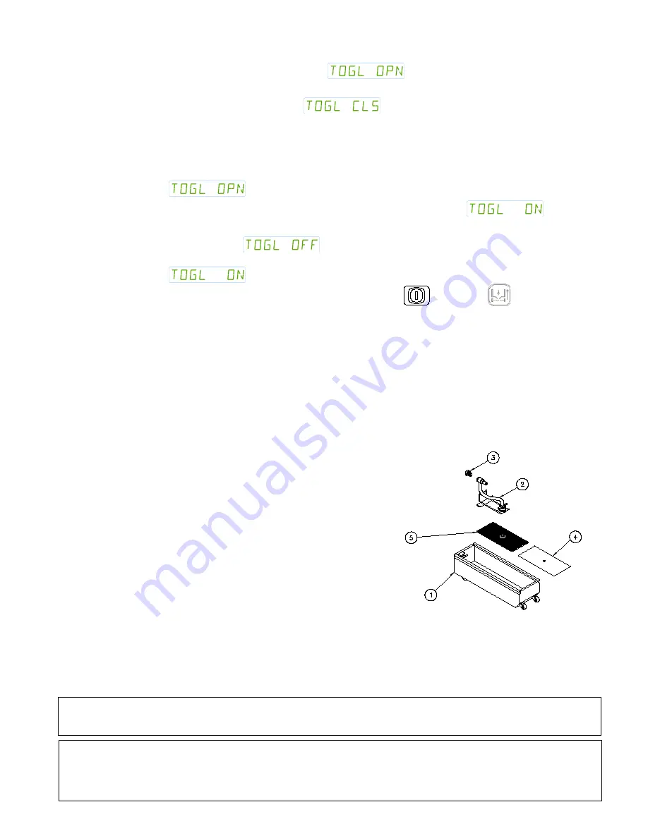
1.  Filter Pan (Solo Filter style shown) 
2.  Filter Pickup Assembly 
3.  Filter Strainer Cap 
4.  Filter Paper 

5. 

Filter Screen


3.  Press the #1 key. The control will display 

 .  

4.  Press the #6 key (YES). The drain valve will open and the oil will drain from the tank into the 

filter pan and the control will display  

5.  With the oil drained into the filter pan you may clean the fry tank. Using a water dampened 

clean cloth, wipe the insides of the fry pot to remove crumbs and debris. Scrub crumb ring in 
frypot with abrasive pad if needed. REMOVE ALL MOISTURE from the tank before 
proceeding to the next step. 

6.  When cleaning has been completed, press the #6 key to close the drain valve. The control will 

display 

 . 

7.  To return the oil to the fry tank, press the L key. The control will display                           . 

8.  Press the #6 key (YES) to turn the filter motor on and begin returning the oil to the fry tank. 

The control will display                            .   

9.  When the tank is full press the #6 key (YES) to turn the filter pump OFF. The control will 

display 

10.  You can now exit the Fryer Control Menu by pressing the           ON/OFF or          Filter key. 

You may want to reheat the oil in the fry tank and perform a full auto filter. Additional filtering procedures, 
settings and control functions can be found in the Control manual that was shipped with your fryer. 


9.1.2.  REPLACING THE FILTER MEDIA (if equipped) 

Refer to the following procedure to replace the filter media if the appliance is equipped with a filter 
drawer. The diagram below shows a Solo Filter style pan and associated parts. Additional filter 
types are available.


1.  Detach the pickup tube from the filter pickup assembly by unscrewing it (counterclockwise), 

at the knurled fitting, from the threaded fitting on the filter screen. 


2.  Slide off the filter paper clip and remove used filter 

paper from filter screen. Clean and completely dry 
pan and pan components. Replace with new filter 
paper, ensuring that the hole in the paper is on the 
top, so that threaded fitting in filter screen 
protrudes through it. 


3.  Fold filter paper to the underside of the filter 

screen and replace filter paper clip. 


4.  Re-attach filter pickup tube to the filter screen by 

screwing it (clockwise) into the threaded fitting in 
filter screen. 


5.  Reinstall the filter pickup assembly into the filter 

system by placing the newly covered screen 
portion of the assembly into the filter pan and 
connecting the quick disconnect on the filter pickup 
assembly into white donut fitting on the left-hand 
side of the appliance. Ensure that it snaps tightly 
and securely into donut fitting. 


Summary of Contents for SGLVRF

Page 1: ... manual for the life of the equipment Model ___________________________ Serial ___________________________ Date Purchased ____________________ ENGLISH Installation Operation Manual REDUCED OIL VOLUME FRYING SYSTEM Covering Models SSHLV14 SSHLV184 SERIES D E I F I T R E C D E S I G N C I R E T I F E D ...

Page 2: ...nce or transfer hot liquids from one container to another when the unit is at operating temperature or filled with hot liquids Serious personal injury could result if skin comes in contact with the hot surfaces or liquids WARNING DO NOT use an open flame to check for gas leaks WARNING DO NOT sit or stand on this appliance The appliance s front panel tank splash back tank cover workshelf drain boar...

Page 3: ...URNER SYSTEM ADJUSTMENT 13 2 12 INITIAL CLEANING 14 3 OPERATION 15 3 1 OPERATIONAL FEATURES 15 3 2 BASIC OPERATIONAL FEATURES 16 3 3 FILLING THE FRY POT 17 3 4 FILLING THE TANK WITH LIQUID SHORTENING 17 4 APPLIANCE START UP 18 4 1 COOKING 19 4 2 COOKING TIPS 19 4 3 BASKET LIFT OPERATION 19 5 FRESH OIL TOP OFF FUNCTION 19 6 AUTOMATIC OIL TOP OFF SYSTEM OPTION 19 7 QUICK STRAIN FILTERING 20 7 1 NON ...

Page 4: ...l Inspection 26 9 4 3 Temperature Control System 26 9 4 4 Filter System If Equipped 26 9 4 5 GAS COMBUSTION SYSTEM 27 9 5 VENTILATION HOOD 27 10 TROUBLESHOOTING 28 10 1 POWER FAILURE 28 10 2 HIGH TEMPERATURE LIMIT SWITCH 28 10 3 DRAIN VALVE INTERLOCK 28 10 4 SELF CLEANING BURNER SYSTEM 29 10 5 RESETTING THE SELF CLEANING BURNER ROLL OUT SWITCH 29 10 6 TROUBLESHOOTING CHARTS 30 10 6 1 Fryer Trouble...

Page 5: ...temperature When the heat demand relay closes it energizes the main burners in the fry pot Near the fryer pot heat tubes the temperature probe and high limit can be found The temperature probe provides a signal to the primary control sensing the oil temperature in the fry pot The fryer is equipped with a manual ADD OIL function that can transfer fresh oil from a JIB Jug in Box located under the fr...

Page 6: ...g the front cover of this manual record the following for warranty service or future reference 1 Your Pitco model number 2 Fryer serial numbers Found on the inner door of each fryer 3 The date purchased from your dealer invoice Once you have completed the above the appliance is ready to be installed 2 2 INSTALLATION CLEARANCES The clearances shown below are for combustible and non combustible inst...

Page 7: ...tation requirements and assure adequate air supply for electrical component ventilation To level the fryer use the following procedure Required tools Large pair of water pump pliers Medium flat blade screwdriver level 12 30 5 cm long max 1 Position appliance in final installed location 2 Apply level across front and then the left and right side of unit determine lowest point and distance to level ...

Page 8: ... line must be installed to meet the local building codes or National Fuel Gas Code ANSI Z223 1 Latest Edition In Canada install the appliance in accordance with CAN CGA B149 1 or 2 and local codes In Australia install the appliance in accordance with AS NZS 5601 Gas line sizing requirements can be determined by your local gas company or in North America by referring to the National Fuel Gas Code A...

Page 9: ... insure that that appliance is disconnected from the fuel line If the fuel line is to be tested at a pressure equal to or less than PSIG 3 45 kPa 34 5 mbar the appliance can be connected during the test but the unit s gas valve must be shut Test all gas line connections for leaks with a solution of soap and water when pressure applied 2 7 Installation Setup The installation of this appliance MUST ...

Page 10: ...qualified installation professional should ensure that the hood is operating properly in conjunction with the appliance Inadequate ventilation may not properly evacuate all appliance emissions Excessive or unbalanced ventilation may cause drafts which could interfere with proper operation of the pilot and burners Leave at least 18 inches 47cm of open space between the flue of the appliance and the...

Page 11: ...ll steps have been followed and executed properly 1 Probe 2 High Temperature Limit WARNING Ensure that your ventilation system does not cause a down draft at the appliance s flue opening A down draft will not allow the appliance to exhaust properly and will cause overheating which may cause permanent damage Damage caused by down drafts will not be covered by the warranty NEVER allow anything to ob...

Page 12: ...o light the appliance 1 Verify that all electrical connections clearances gas connections ventilation requirements and gas pressures have been properly implemented tested adjusted and checked for compliance in accordance with the instructions and requirements in Section 2 of this document prior to proceeding 2 Open the gas supply valves to the appliance 3 Turn the gas valve knob to the ON position...

Page 13: ...The main burners must be adjusted to deliver optimum flame Refer to the following procedure to adjust the main burners 1 Ensure that the main gas valve is shut off remove the burner pressure tap plug and connect an accurate pressure gauge range of 0 16 W C 39 85mbar 3 98kPa in 0 1 25mbar 02kPa increments or manometer 2 Turn on this and all appliances connected to the gas supply line and light thei...

Page 14: ...aces 4 When cleaning is complete rinse the inside of the tank thoroughly with cool water Continue to rinse the tank until the cleaner has been completely and thoroughly rinsed from the tank 5 Using a clean dry cloth wipe out all of the water in the fry tank 6 Using a clean cloth and food grade cleaner clean the bread and batter station and or filter pan if equipped If the appliance can t be adjust...

Page 15: ...iance WARNING Before operating the fryer check that tipping restraints or other features to prevent tipping are installed and mechanically sound Splashing of hot liquid may occur if adequate means of securing the fryer in place are not used 3 1 OPERATIONAL FEATURES The diagram below outlines some of the key operational components of your appliance Refer to the following sections of this manual to ...

Page 16: ...t button RED Press to reset SEE WARNING BELOW 8 Drain Outlet Swings out to ease shortening disposal CAUTION Extremely HOT when in use 9 Pump Strainer Helps prevent debris from jamming filter pump if filter paper rips or is installed poorly 10 Filter Pump Circuit Breaker Protects pump motor from over current SEE WARNING BELOW 11 Frypot High Limit Reset Button Shown on page 28 Press to reset 12 Data...

Page 17: ...place oil shortening that is smoking or foams when cooking Old heavily used oil shortenings have reduced flash point and are prone to surge boiling Cooking with old heavily used oil shortening may create dangerous conditions WARNING Do not overload the fry baskets or allow the oil level to exceed the MAX line while cooking Wet product or too much oil in the frypot can lead to surge boiling and ove...

Page 18: ...il and give you no faster cooking At 205 C 401 F to 210 C 410 F the life of the oil is only one third of its life at 190 C 374 F In addition increased decomposition causes the oil to smoke badly even if the temperature is lowered to 190 C 374 F again High temperatures give you no advantage cost you money and increase the fire danger TEMPERATURE DELL OLIO Mantenere la temperatura dell olio nella fr...

Page 19: ...the cook tank when a product key is pressed At the end of the preset cooking time the basket lift will raise the basket out of the cook tank Cancelling the cook by pressing and holding the cook timer button will raise the basket out of the oil Cook timer keys L through 5 will operate the right hand basket lift Keys 6 through R will operate the left hand basket lift 5 FRESH OIL TOP OFF FUNCTION To ...

Page 20: ...ump will refill the fry tank 5 When bubbles appear in oil press the TANK FILL key to turn pump to OFF 6 FILTER ONLY ONE TANK AT A TIME the filter pan may overflow 7 2 AUTO FILTER MODELS WARNING Before filtering ensure that filter pan is in place and empty Wear proper personal protective equipment while filtering 1 Ensure that oil temperature is above Filter Temperature Press the Filter button on t...

Page 21: ...NG At least daily a complete filter is required Make sure a clean filter is installed every day For manual filtering refer to the following procedure 1 Ensure that the filter pan is in place and empty Turn the appliance OFF Pull the blue drain handle to drain oil shortening from the cooker tank into the filter pan 2 Using a water dampened clean cloth wipe the insides of the fry pot to remove crumb...

Page 22: ...lter pump OFF The control will display 10 You can now exit the Fryer Control Menu by pressing the ON OFF or Filter key You may want to reheat the oil in the fry tank and perform a full auto filter Additional filtering procedures settings and control functions can be found in the Control manual that was shipped with your fryer 9 1 2 REPLACING THE FILTER MEDIA if equipped Refer to the following proc...

Page 23: ...nk using a Scotchbrite or other abrasive pad DO NOT use steel wool 5 Wipe residue with a clean damp cloth and carefully dry any remaining oil shortening droplets from the tank before returning oil shortening into the tank 6 Clean and dry baskets tank rack and basket hanger before reinstalling 9 1 5 CLEANING THE CABINET 1 Wipe any spilled oil shortening dust and lint from the cabinet exterior with ...

Page 24: ...eep your equipment safe and at peak performance If you are producing high quantities of fried food and or frying heavily battered food it may be necessary to clean these components more than once a month 9 3 1 BOIL OUT PROCEDURE Wear protective gloves and clothing when cleaning and draining the appliance Oil shortening water or steam may spatter and will cause injury to personnel 1 Read the operat...

Page 25: ...ater and residue with a clean dry cloth 15 Clean and dry baskets tube rack and basket hanger before reinstalling 16 Close the drain valve and fill the cooker tank with oil shortening Manual models push the blue handle in The drain will close Automatic models press the 6 key YES The drain will close the control will display To exit the Fryer Control Menu press the ON OFF key or the Filter key 17 Yo...

Page 26: ... hood down draft currents Check drain filtration system if equipped for leaks Check for missing fryer parts i e cover strips Check for missing fasteners 9 4 3 Temperature Control System Check electrical connections and harnesses Check temperature probes and limits for carbon build up and plating Clean as required Check proper mounting of probes and sensors and all fasteners are secure Check thermi...

Page 27: ...k incoming gas pressure to the appliance under static and dynamic conditions Check ignition system and adjust pilot flame as required Check flame sensor reading Check gap spacing and clean igniter Recheck for gas leaks after inspection 9 5 VENTILATION HOOD Proper ventilation hood operation is very important for the correct operation of this appliance and the safety of personnel The ventilation hoo...

Page 28: ...it the appliance will stop heating if the tank drain valve is opened The appliance will turn off and scroll a message DRN TRN OFF Refer to the following procedure to resume operation after the drain valve interlock is tripped 1 Turn the computer OFF if not already OFF 2 Close the tank drain valve Manual models push the blue handle in The drain will close Automatic models press and hold the key to ...

Page 29: ...and ready for startup 4 If the SCBS roll out switch continues to trip have the appliance inspected by an Authorized Professional Event Duration Indication Turn appliance ON N A Control Illuminates pilot sparks and ignites Pre Purge pulse is initiated Pre Purge Pulse 2 seconds Appliance operates briefly and stops Pilot remains lit Interwaiting period 1 5 seconds Appliance does not operate Pilot rem...

Page 30: ... be turned on Faulty computer Contact Authorized Service Company Problem Possible Causes Corrective Actions Filter pump does not activate The filter pump circuit breaker has tripped Reset the circuit breaker The thermal overload on the pump motor has tripped Allow the motor to cool and reset the thermal overload on the motor Oil Shortening is returning to the tank slowly or not at all Dirty filter...

Page 31: ...technician Temperature probe is shorted Contact a qualified service technician This message indicates that oil in the vat is in need of polishing Operators may depending on settings polish now or defer the polish filter opertion for a later time This message indicates that the computer has lost communication with the autofilter control board and oil management operations are suspended Normal cooki...

Page 32: ... adjusted to operate correctly contact In the event of problems with or questions about your order please contact the Pitco Frialator factory at 603 225 6684 World Wide Website Address www pitco com In the event of problems with or questions about your equipment please contact the Pitco Frialator Authorized Service and Parts representative ASAP covering your area or contact Pitco at the numbers li...

Reviews: