120
1
2
3
4
1
2
3
4
C
D
F
A
B
E
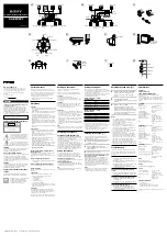
XV-DV515
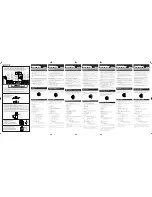
1
Remove the two screws.
2
Remove the two flexible cables.
3
Remove the Loading Mecha. Assy.
4
Reverse the Loading Mecha. Assy.
8
Reattatch the CONTROL Assy.
9
Reattatch the front panel section.
Arrange the Loading Mecha. Assy and the DVDM Assy as shown in the photo below.
10
11
Connect the two jig cables.
5
Remove the three hooks.
6
Remove the two screws.
7
Remove and reverse the DVDM Assy.
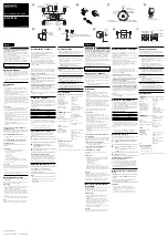
Diagnosis of DVDM Assy
5
1
1
6
6
Loading Mecha. Assy
CONTROL Assy
TRADE 2 Assy
Jig cable (GGD1266)
Front panel section
DVDM Assy
6CH AMP Assy
POWER Assy
Spacer
Spacer
Spacer
Loading Mecha. Assy
(Reverse state)
DVDM Assy
3
2
2
7
5
8
9
5
5
Bottom View (Rear side)
Diagnosis
Jig cable (GGD1160)
Jig cable (GGD1222)
11
11
CN923
CN901
CN8801
CN8801
CN5102
CN5102
B
J
D
H
F
B
Ground Line
(Chassis–DSP Holder(DSP GND))