background image


The System Setup menu

07


34


En


1

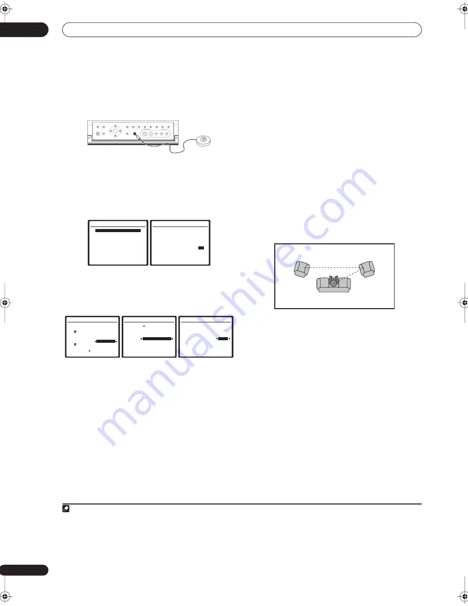
Connect the microphone to the MCACC 


SETUP MIC


jack on the front panel. 


Make sure there are no obstacles between the speakers 
and the microphone.

If you have a tripod, use it to place the microphone so that 
it’s about ear level at your normal listening position. 
Otherwise, place the microphone at ear level using a 
table or a chair.


2

Select ‘Auto MCACC’ from the System Setup menu 

then press 


ENTER


.

3

Make sure ‘Normal (SB)’ is selected,


1


 select an 

MCACC preset


2


 then select OK.


For a fully customized Auto MCACC setup, select 


Option


and set the following parameters:


Auto Mode


 – The default is 


ALL


 (recommended), but 

you can limit the system calibration to only one 

setting (to save time) if you want.


3


 The available 

options are 


ALL


ALL (Keep SPsetting)


,


4


Speaker 

Setting


Channel Level


Speaker Distance


Acoustic Cal EQ


, and 


Aco Cal EQ Pro.


THX Speaker


(only available when the Auto Mode 

above is 


ALL


 or


 Speaker Setting


)


 – Select 


YES


 if you 

are using THX speakers (set all speakers to 


SMALL


), 

otherwise leave it set to 


NO


.


EQ Type


(only available when the Auto Mode above is 


Acoustic Cal EQ


or 


Aco Cal EQ Pro.


)


 – This 

determines how the frequency balance is adjusted. 


ALL CH ADJUST


 (default) is a ‘flat’ setting where all 

the speakers are set individually so no special 

weighting is given to any one channel. Optionally,


5


FRONT ALIGN


 sets all speakers in accordance with 

the front speaker settings (no equalization is applied 
to the front left and right channels), and 


OFF


 (only 

available when 


ALL


 is selected) allows you to save 

calibration settings (such as speaker distance and 
channel level) with no EQ or standing wave 
adjustment to your selected preset.


Multi-Point


(only available when the Auto Mode 

above is 


Acoustic Cal EQ


or 


Aco Cal EQ Pro.


)


 – In 

addition to measurements at the listening position, 
you can use two more reference points for which test 
tones will be analyzed for standing waves. This is 
useful if you want to get a balanced ‘flat’ calibration 

for several seating positions in your listening area.


6


Place the microphone at the reference point 
indicated on-screen and note 


the last microphone 

placement will be at your main listening position:


When you’re finished settings the options, press 


RETURN


 to go back to the Auto MCACC main setup.


4

Follow the instructions on-screen.


• Make sure the microphone is connected.

• If you’re using a subwoofer, it is automatically 

detected every time you switch on the system. Make 
sure it is on and the volume is turned up.

• See 


Problems when using the Auto MCACC Setup


 on 

page 9 for notes regarding high background noise 
levels and other possible interference.


5

Wait for the Auto MCACC Setup to finish outputting 

test tones.


A progress report is displayed on-screen while the 
receiver outputs test tones to determine the speakers 
present in your setup. Try to be as quiet as possible while 
it’s doing this. 

• Do not adjust the volume during the test tones. This 

may result in incorrect speaker settings.

Note


1 If you are planning on bi-amping your front speakers, or setting up a separate speaker system in another room, read through 


Surround back speaker set-

ting


 on page 35 and make sure to connect your speakers as necessary before continuing to step 4.

2 The six MCACC presets are used for storing surround sound settings for different listening positions. Simply choose an unused preset for now (you can 
rename it later in 


Data Management


 on page 41).

3 The 


Aco Cal EQ Pro.


 measurement is also taken when 


ALL


 is selected. See 


Professional Acoustic Calibration EQ


 on page 38 for more on this.

4 The 


ALL (Keep SPsetting)


 option allows you to calibrate your system while leaving your current speaker setting (page 42) unchanged.

SPEAKERS

(TUNE +)

ENTER

(TUNE –)

PHONES

AV
PARAMETER

SETUP

(ST –)

(ST +)

TUNER

EDIT

BAND

CONTROL

ON/OFF

VIDEO

SELECT

SIGNAL
SELECT

SBch 

PROCESSING

STEREO

VIDEO/GAME 2 INPUT

DIGITAL IN

S-VIDEO

VIDEO

L

R

AUDIO

MULTI – ROOM & 
SOURCE/REC SEL

MCACC

SETUP MIC

RETURN

System  Setup

1.Auto  MCACC

2.Surr  Back  System
3.Manual  MCACC
4.Data  Management
5.Manual  SP  Setup
6.Input  Setup
7.Other  Setup

 : Exit  

1.Auto  MCACC

Surr  Back  System
  [          Normal (SB)           ]  
Data  Save  to
           [M1.  MEMORY  1 

]

Setting  Start? 

[

OK

]  


[Option]  

ENTER:Next 

:Cancel  

1.Auto  MCACC  Option

Auto  Mode
        [ 

ALL 

 ]


Speaker settings


will be updated.

THX  Speaker    


NO  


 If  you  are using  THX


speakers,  select  YES.

(   Next )

 : Return  to  Auto  MCACC

1. Auto  MCACC  Option


(   Back )

  EQ  Type : FRONT ALIGN
    Data  Save  to


M2.  MEMORY  2 


  EQ  Type : OFF
    Data  Save  to
   

[ – – . – – – 

]

: Return  to  Auto  MCACC

1.Auto  MCACC  Option

Auto  Mode
       [  Aco  Cal  EQ  Pro. 

]

EQ  Type
 

[ALL  CH  ADJUST]  

Multi-Point                    

NO


 : Return  to  Auto  MCACC


5 If you selected 


ALL


 as your 


Auto Mode


 setting, you can specify the MCACC preset where you want to save the 


FRONT ALIGN


 and/or 


OFF


 settings.

6 Switch the 


Multi-Point


 setting 


OFF

 if you only use one listening position.

Main listening 

position

2nd reference

point

3rd reference

point

1

2

3

VSX_AX4AVi_G.book.fm 34 ページ 2005年7月6日 水曜日 午後4時12分

Summary of Contents for VSX-AX2AV-G

Page 1: ...AUDIO VIDEO MULTI CHANNEL RECEIVER VSX AX4AVi G VSX AX2AV G Operating Instructions ...

Page 2: ...e or shock hazard do not place any container filled with liquid near this equipment such as a vase or flower pot or expose it to dripping splashing rain or moisture D3 4 2 1 3_A_En VENTILATION CAUTION When installing this unit make sure to leave space around the unit for ventilation to improve heat radiation at least 60 cm at top 10 cm at rear and 30 cm at each side WARNING Slots and openings in t...

Page 3: ... the AC power cord Use a medium size screwdriver to change the voltage selector switch D3 4 2 1 5_En Changing the TV format setting If the System Setup menu is not displayed correctly it may be that the TV system is set incorrectly for your country or region With the receiver in standby press STANDBY ON while holding down the SIGNAL SELECT button The display shows the new setting PAL or NTSC This ...

Page 4: ...mprove FM reception 20 Using an external antenna to improve AM reception 20 Plugging in the receiver 21 04 Controls and displays Front panel 22 Operating range of remote control unit 23 Display 24 Remote control 25 05 Listening to your system Auto playback 27 Listening in surround sound 27 Standard surround sound 27 Using the Home THX modes 28 Using the Advanced surround effects 28 Listening in st...

Page 5: ...r a video recording 64 Playing a different source when recording 64 Reducing the level of an analog signal 65 Watching video and audio sources independently 65 Using the sleep timer 65 Dimming the display 65 Switching the speaker impedance 65 Checking your system settings 65 Resetting the system 66 Default system settings 66 11 Controlling the rest of your system Setting the remote to control othe...

Page 6: ... field This may interfere with the sound in direct sunlight in damp or wet areas in extremely hot or cold areas in places where there is vibration or other movement in places that are very dusty in places that have hot fumes or oils such as a kitchen Loading the batteries Caution Incorrect use of batteries may result in such hazards as leakage and bursting Observe the following precautions Never u...

Page 7: ...your DVD player your subwoofer and the TV Make sure you ve set the video input on your TV to this receiver Check the manual that came with the TV if you don t know how to do this Set the subwoofer volume to a comfortable level 4 Use the on screen automatic MCACC setup to set up your system See Automatically setting up for surround sound MCACC below for more on this 5 Play a DVD and adjust the volu...

Page 8: ...ible to adjust these settings manually using the System Setup menu starting on page 33 8 Note 1 You can t use the System Setup menu when the iPod input source is selected in either the main or sub room 2 If you cancel the Auto MCACC Setup or leave an error message for over three minutes the screen saver will appear 3 If you are planning on bi amping your front speakers or setting up a separate spe...

Page 9: ... below Phase Control technology provides coherent sound reproduction through the use of phase matching4 for an optimal sound image at your listening position The default setting is on and we recommend leaving Phase Control switched on for all sound sources Press PHASE PHASE CONTROL to switch on phase correction The PHASE CONTROL indicator on the front panel lights Note 1 Make sure that the TV s vi...

Page 10: ...2 VSX AX4AVi only Use to connect other i LINK audio devices for high resolution multichannel digital audio input output Using the i LINK interface on page 48 5 HDMI connectors x3 Two inputs and one output for high quality audio video connection to compatible HDMI devices Connecting using HDMI on page 47 6 Remote input multi room and source Use for connection to an external remote control sensor fo...

Page 11: ...on to the main front center surround and surround back speakers Installing your speaker system on page 17 20 AC IN inlet Connect the supplied power cord here 21 Voltage selector switches Use these to match the voltage coming into the receiver with the voltage in your country or region Voltage selector on page 3 When making cable connections To avoid hum do not lay connected cables over the top of ...

Page 12: ... inputs Connect using a stereo RCA phono jack cable If your DVD player has multichannel analog outputs you can connect these instead See also Connecting the multichannel analog inputs on page 51 TV VIDEO IN S VIDEO IN S400 AUDIO S400 MULTI ROOM SOURCE RECSEL OUT1 ROOM3 ZONE3 OUT2 USB AUDIO IN IN1 SAT IN2 DVR VCR 1 IN3 DVR VCR 2 IN4 CD R 1 2 1 3 1 4 IN1 DVD LD IN2 IN1 DVD LD IN2 TV IN1 IN1 IN2 IN3 ...

Page 13: ...n page 60 3 If your satellite cable receiver doesn t have a digital audio output you can skip this step S400 AUDIO S400 MULTI ROOM SOURCE RECSEL OUT1 ROOM3 ZONE3 OUT2 USB AUDIO IN IN1 SAT IN2 DVR VCR 1 IN3 DVR VCR 2 IN4 CD R 1 2 1 3 1 4 IN1 DVD LD IN2 IN1 DVD LD IN2 TV IN1 IN1 IN2 IN3 IN3 OUT MULTI ROOM SOURCE MULTI ROOM SOURCE MONITOR OUT 12V TRIGGER ROOM2 ZONE2 ROOM2 ZONE2 FMUNBAL75Ω AMLOOP MONI...

Page 14: ...our TV or monitor Use a three way component video cable Note 1 In order to record you must connect the analog audio cables the digital connection is for playback only If your video component doesn t have a digital audio output you can skip this step 2 If your recorder only has a coaxial digital output you can connect it to one of the coaxial inputs on this receiver using a coaxial digital audio ca...

Page 15: ...MONITOR OUT 12V TRIGGER ROOM2 ZONE2 ROOM2 ZONE2 FMUNBAL75Ω AMLOOP MONITOR OUT OUT CD CD R TAPE DVD LD TV SAT VIDEO1 GAME1 OUT DVR VCR1 DVR VCR2 OUT IN IN VIDEO VIDEO AUDIO S VIDEO IN IN IN FR FL SUBW M IN SUR ROUND SURROU B CONTROL OUT PHONO IN IN IN IN ROOM2 ZONE2 IN DCOUT12VTOTAL50mAMAX 1 2 IN2 CD IN1 IN2 OUT Y PB PR Y PB PR Y PB PR Y PB PR DIGITAL COMPONENT VIDEO ASSIGNABLE ASSIGNA BLE 1 2 ASSI...

Page 16: ...o inputs AUDIO L R and an optical digital audio input DIGITAL You can use these connections for any kind of audio video component but they are especially convenient for portable equipment such as camcorders video games and portable audio video equipment Select these inputs using INPUT SELECT remote or the INPUT SELECTOR dial front panel to select VIDEO GAME 2 VSX AX4AVi 1 3 IN1 DVD LD IN2 TV IN1 I...

Page 17: ...ay cause the power to cut off as a safety measure S400 AUDIO S400 MULTI ROOM SOURCE RECSEL OUT1 ROOM3 ZONE3 OUT2 USB AUDIO IN IN1 SAT IN2 DVR VCR 1 IN3 DVR VCR 2 IN4 CD R 1 2 1 3 1 4 IN1 DVD LD IN2 IN1 DVD LD IN2 TV IN1 IN1 IN2 IN3 IN3 OUT MULTI ROOM SOURCE MULTI ROOM SOURCE MONITOR OUT 12V TRIGGER ROOM2 ZONE2 ROOM2 ZONE2 FMUNBAL75Ω AMLOOP MONITOR OUT OUT CD CD R TAPE DVD LD TV SAT VIDEO1 GAME1 OU...

Page 18: ...e interference such as discoloration of the picture when the TV is switched on If you do not have magnetically shielded speakers and notice discoloration of the TV picture move the speakers farther away from the TV If you re using a center speaker place the front speakers at a wider angle If not place them at a narrower angle Place the center speaker above or below the TV so that the sound of the ...

Page 19: ...on indicated fig A Clip the loop into the stand fig B It s possible to fix the AM antenna to a wall fig C Before fixing make sure that the reception is satisfactory 2 Pull off the protective shields of both AM antenna wires 3 Press the AM LOOP antenna terminal tabs to open and insert one wire into each terminal 4 Release the tabs to secure the AM antenna wires 5 Place the AM antenna on a flat surf...

Page 20: ...able used with an external FM antenna 1 Cut and strip the coaxial cable to the specification shown in the diagram 2 Open the adaptor body by pulling apart the tabs on either side 3 Insert the cable as shown then use a pair of pliers to wrap the end of the wire around the binding post Snip off the excess wire 4 Use pliers to secure the cable by pinching the clamps together as shown 5 Push the body ...

Page 21: ...r give you an electric shock Check the power cord once in a while If you find it damaged ask your nearest Pioneer authorized independent service company for a replacement Do not use any power cord other than the one supplied with this unit Do not use the supplied power cord for any purpose other than that described below The receiver should be disconnected by removing the mains plug from the wall ...

Page 22: ...ol unit on page 23 6 MCACC indicator Lights when one of the MCACC presets page 29 is selected 7 Digital Precision Processing indicator Lights to indicate digital processing for example it disappears when Pure Direct page 29 is on or when listening through the multichannel analog inputs 8 Character display See Display on page 24 SPEAKERS TUNE ENTER TUNE PHONES AV PARAMETER SETUP ST ST TUNER EDIT BA...

Page 23: ...e 56 You will also need to use the REC SEL controls when recording a source see Making an audio or a video recording on page 64 19 VIDEO SELECT Press repeatedly to select the video source page 65 20 SIGNAL SELECT Use to select an input signal page 29 21 SBch PROCESSING Selects the surround back channel mode page 30 or virtual surround back mode page 30 22 STEREO Switches to stereo playback page 29...

Page 24: ... stereo mode MONO Lights when the mono mode is set using the MPX button 10 Master volume level Shows the overall volume level 80dB indicates the minimum level and 12dB indicates the maximum level 11 Input source indicators Light to indicate the input source you have selected 12 STREAM DIRECT Lights when Direct Pure Direct is selected page 29 13 Speaker indicators Indicate the current speaker syste...

Page 25: ...ton controls can be accessed after you have selected the corresponding input source button DVD DVR1 SAT etc The BAND and T EDIT tuner controls are explained from page 31 Press RECEIVER first to access the following controls AV PARAMETER Use to access the AV options page 63 SETUP Use to access the System Setup menu page 33 CH LEVEL Press repeatedly to select a channel then use to adjust the level p...

Page 26: ...ET See Selecting preset codes directly on page 67 LEARNING See Programming signals from other remote controls on page 67 MULTI OP See Multi Operation and System Off on page 69 SYS OFF See Multi Operation and System Off on page 69 DIRECT F See Direct function on page 69 RENAME See Renaming input source names on page 69 ERASE See Erasing one of the remote control button settings on page 68 RESET See...

Page 27: ...to video games 2 PRO LOGIC 4 1 channel surround sound sound from the surround speakers is mono Neo 6 CINEMA 6 1 channel sound especially suited to movie sources Neo 6 MUSIC 6 1 channel sound especially suited to music sources6 With multichannel sources if you have connected surround back speaker s and have selected SBch ON you can select according to format 2 Pro Logic IIx MOVIE See above only ava...

Page 28: ...oundtracks but some modes are also suited for music sources Try different settings with various soundtracks to see which you like Press ADV SURR ADVANCED SURROUND repeatedly to select a listening mode 2 ACTION Designed for action movies with dynamic soundtracks SCI FI Designed for science fiction with lots of special effects DRAMA Designed for movies with lots of dialog MUSICAL Creates a concert h...

Page 29: ...ng to the source component Each press cycles through the options as follows AUTO This is the default setting The receiver selects the first available signal in the following order HDMI DIGITAL ANALOG ANALOG Selects an analog signal DIGITAL Selects an optical or coaxial digital signal HDMI Selects an HDMI signal 5 Selects an i LINK signal VSX AX4AVi only Note 1 There are cases where a brief noise i...

Page 30: ... was originally encoded you can have the receiver only apply this effect to 6 1 encoded sources like Dolby Digital EX or DTS ES 2 The table indicates when you will hear the virtual surround back channel Virtual surround back channel is active Press SBch SBch PROCESSING repeatedly to cycle the virtual surround back channel options Each press cycles through the options as follows VirtualSB ON Virtua...

Page 31: ...of the radio station For example to tune to 106 00 FM press 1 0 6 0 0 If you make a mistake halfway through press D ACCESS twice to cancel the frequency and start over Saving station presets If you often listen to a particular radio station it s convenient to have the receiver store the frequency for easy recall whenever you want to listen to that station This saves the effort of manually tuning i...

Page 32: ... If no character is input a space is input The name is stored when ENTER is pressed after choosing the fourth character Tip To erase a station name simply repeat steps 1 3 and input four spaces instead of a name Once you have named a station preset you can press DISP when listening to a station to switch the display between name and frequency Listening to station presets You will need to have some...

Page 33: ... Setup menu on page 61 Automatic MCACC Expert If your setup requires more detailed settings than those provided in Automatically setting up for surround sound MCACC on page 7 you can customize your setup options below You can calibrate your system differently for up to six different MCACC presets3 which are useful if you have different listening positions depending on the type of source for exampl...

Page 34: ...he microphone is connected If you re using a subwoofer it is automatically detected every time you switch on the system Make sure it is on and the volume is turned up See Problems when using the Auto MCACC Setup on page 9 for notes regarding high background noise levels and other possible interference 5 Wait for the Auto MCACC Setup to finish outputting test tones A progress report is displayed on...

Page 35: ...ge 43 for more on this Speaker Distance The distance of your speakers from the listening position see page 44 for more on this 3 Standing Wave Filter settings to control lower boomy frequencies see page 37 for more on this Acoustic Cal EQ Adjustments to the frequency balance of your speaker system based on the acoustic characteristics of your room see page 38 for more on this Press ENTER after you...

Page 36: ... notes regarding high background noise levels and other possible interference If you re using a subwoofer switch it on and turn up the volume to the middle position 1 Select Manual MCACC from the System Setup menu See Making receiver settings from the System Setup menu on page 33 if you re not already at this screen 2 Select the setting you want to adjust If you re doing this for the first time yo...

Page 37: ...tstretched pointing at each speaker Try to make the two tones sound as if they are arriving simultaneously at a position slightly in front of you and between your arm span 1 When it sounds like the delay settings are matched up press to confirm and continue to the next channel For comparison purposes the reference speaker will change depending on which speaker you select If you want to go back and...

Page 38: ...ing Use the buttons to select the channel Use the buttons to select the frequency and to boost or cut the EQ When you re finished go back to the top of the screen and use the buttons to select the next channel The OVER indicator shows in the display if the frequency adjustment is too drastic and might distort If this happens bring the level down until OVER disappears from the display Tip Changing ...

Page 39: ...ration and professional calibration the gray circles represent the point at which the microphone captures the sound for frequency analysis As soon as audio is output from your speaker system it is influenced by room characteristics such as walls furniture and the dimensions of the room The sooner the frequency analysis the less it is influenced by the room We recommend an earlier time setting of 2...

Page 40: ...the buttons to select the channel and the frequency you want to check Use the buttons to go back and forth between the two Note that the markers on the vertical axis indicate decibels in 2dB steps 5 If you selected Advanced EQ Setup input the time setting you want to use for calibration then select Go Select Start from the next screen Based on the reverb measurement above you can choose the time p...

Page 41: ...ou want to check Use the buttons if necessary to switch speakers settings 4 Press RETURN to go back to the Data Check menu repeating steps 2 and 3 to check other settings 5 When you re finished press RETURN You will return to the Data Management setup menu Copying MCACC preset data If you want to manually adjust the Acoustic Calibration EQ see Manual MCACC setup above we recommend copying your cur...

Page 42: ...utomatically setting up for surround sound MCACC on page 7 it isn t necessary to make all of these settings Caution The test tones used in the System Setup are output at high volume 1 Select Manual SP Setup then press ENTER 2 Select the setting you want to adjust If you are doing this for the first time you may want to adjust these settings in order Speaker Setting Specify the size and number of s...

Page 43: ...er and adjust individual channel levels Auto Adjust channel levels as the test tone moves from speaker to speaker automatically 3 Confirm your selected setup option The test tones will start after you press ENTER Note 1 If you select SMALL for the front speakers the subwoofer will automatically be fixed to YES Also the center and surround speakers can t be set to LARGE if the front speakers are se...

Page 44: ...nual SP Setup menu The current setting is displayed When OFF is displayed the attenuator is off bass output is not affected 2 Select a setup option Setting Start The volume is set to 60dB a test tone plays back and you make the setting Setting Clear Clears any previous setting and switches limiting off 3 If you selected Setting Start use to adjust the test tones and specify the bass peak level the...

Page 45: ...em see About THX on page 81 it is required that you make the setting See Placing the speakers on page 18 for more on THX speaker placement 3 1 Select THX Audio Setting from the Manual SP Setup menu 2 Specify the distance of your surround back speakers from each other 0 0 0 3m Surround speakers within 30cm apart best for THX surround sound 0 3 1 2m Surround speakers between 30cm and 1 2m apart 1 2m...

Page 46: ... to previous next levels 3 Continue browsing until you arrive at what you want to play then press to start playback 4 Navigation through categories on your iPod looks like this Playlist Song Artist Album Song Album Song Song Note 1 This system is compatible with an iPod iPod mini and iPod Photo portable device third generation and above however compatibility may vary depend ing on the software ver...

Page 47: ...the song playback information displayed During playback press to skip to previous next playlist when browsing press to move to previous next levels TOP MENU Press to return to the iPod Top menu screen RETURN Press to return to the previous level Note 1 An HDMI connection can only be made with DVI equipped components compatible with both DVI and High Bandwidth Digital Content Protection HDCP If you...

Page 48: ...gnals one connector instead of several cables and connectors and communication between the AV source and AV devices such as DTVs HDMI the logo and High Definition Multi media Interface are trademarks or registered trademarks of HDMI licensing LLC Using the i LINK interface VSX AX4AVi only If you have a component with an i LINK connector you can connect it to this receiver using an i LINK cable Sin...

Page 49: ...8AVi i LINK If a connected devices cannot output playback a source using the i LINK connection is displayed after the input device name e g DV 868AVi Non compatible devices cannot be assigned to inputs When the cables for an assigned input device become loose or the power is cut to the device an asterisk appears before the device name e g DV 868AVi CD 3 When you re finished press RETURN You will r...

Page 50: ...ation This receiver is DTCP Digital Transmission Content Protection compliant so you can play DVD A DVD Video and SACD i LINK audio When setting up an i LINK network it s important that the components form an open ended chain fig 1 or a tree fig 2 The system will not work if the connected components form a loop If a loop is detected the message LOOP CONNECT shows in the display Figs 3 and 4 show c...

Page 51: ... analog audio you ll need to switch the input signal selector to MULTI CH INPUT see Selecting the multichannel analog inputs above for more on this 2 When playback from the multichannel inputs is selected you can t use Midnight Loudness Dialog Enhancement or the SIGNAL SELECT and ANA LOG ATT buttons as well as any of the listening modes including STEREO and the surround back channel processing Whe...

Page 52: ...e 65 if you plan to use speakers with an impedance of less than 8Ω After selecting 2nd Zone in Surround back speaker setting on page 35 you can use the speakers connected to the surround back B speaker terminals on the rear panel to listen to stereo playback in another room See Switching the speaker system below for the listening options with this setup 1 Connect a pair of speakers to the surround...

Page 53: ...surround back speaker terminals output the same audio it doesn t matter which set front or surround back is powering which part High or Low of the speaker Make sure that the connections are properly inserted 2 Select the Front Bi Amp setting from the Surr Back System menu See Surround back speaker setting on page 35 to specify how you re using the surround back speaker terminals Caution Most speak...

Page 54: ...NALOG Front channel amplifier INPUT L R ANALOG Surround channel amplifier INPUT L R ANALOG Surround back channel amplifier INPUT ANALOG Powered subwoofer INPUT ANALOG Center channel amplifier mono Note 1 You can t use sound controls such as the tone controls or Midnight listening or any surround modes with a separate amplifier in the sub room You can however use the features available with your su...

Page 55: ...HDMI R L R R R R L Sub room Main room IN1 DVD LD IN1 IN1 IN2 OUT MULTI ROOM SOURCE MULTI ROOM SOURCE MONITOR OUT 12V TRIGGER ROOM2 ZONE2 ROOM2 ZONE2 FMUNBAL75Ω AMLOOP MONITOR OUT OUT C CD TA DVD LD TV IN IN O IN IN ROOM2 ZONE2 IN DCOUT12VTOTAL50mAMAX 1 2 OUT MULTI ROOM SOURCE IR DMI R L Note 1 Only one sub room is possible if you connect the OUT1 ROOM3 ZONE3 digital output to your second sub room ...

Page 56: ...receiver setup on page 62 Note 1 Note that when recording this also selects the RECOUT input source See Making an audio or a video recording on page 64 for more on this 2 If the receiver is in standby the display is dimmed and ZONE and your selected sub room s continue to show in the display SPEAKERS TUNE ENTER TUNE PHONES AV PARAMETER SETUP ST ST TUNER EDIT BAND CONTROL ON OFF VIDEO SELECT SIGNAL...

Page 57: ...1 ROOM3 ZONE3 OUT2 USB AUDIO IN IN1 SAT IN2 DVR VCR 1 IN3 DVR VCR 2 IN4 CD R 1 2 1 3 1 4 IN1 DVD LD IN2 IN1 DVD LD IN2 TV IN1 IN1 IN2 IN3 IN3 OUT MULTI ROOM SOURCE MULTI ROOM SOURCE MONITOR OUT 12V TRIGGER ROOM2 ZONE2 ROOM2 ZONE2 FMUNBAL75Ω AMLOOP MONITOR OUT OUT CD CD R TAPE DVD LD TV SAT VIDEO1 GAME1 OUT DVR VCR1 DVR VCR2 OUT IN IN VIDEO VIDEO AUDIO S VIDEO IN IN IN FR FL SUBW CENTER MULTI CH IN...

Page 58: ...ays on page 62 for more on setting up the receiver Important The additional SR features do not work when the iPod function is selected 1 Make sure that the plasma display and this receiver are switched on and that they are connected with the SR cable See Using this receiver with a Pioneer plasma display above for more on connecting these components Make sure you have also selected the display inpu...

Page 59: ...connected from the power outlet when you do this 1 Use a commercially available cable to connect the RS 232C jack on your computer to the 9 pin RS 232C jack on this receiver See the documentation provided with the Advanced MCACC application for more information Advanced MCACC output using your PC Before continuing make sure you have completed steps 1 3 in Professional Acoustic Calibration EQ on pa...

Page 60: ...after doing so see Checking the i LINK inputs on page 49 2 6 When you re finished select Next to continue to the next screen The second screen of the Input setup has three optional settings Input name You can choose to rename the input function for easier identification Select Rename to do so or Default to return to the system default RECEIVER SOURCE SYSTEM OFF INPUT SELECT DVD SAT VIDEO1 TVCONT D...

Page 61: ...ecify your volume setting for a multi room setup and your IR receiver type see Multi Room and IR receiver setup below SR Setup Specify how you want to control your Pioneer plasma display see SR Setup for Pioneer plasma displays below OSD Adjustment Adjust the position of the on screen display on your TV see OSD Adjustment below iLINK Check VSX AX4AVi only Check which i LINK equipped components you...

Page 62: ...g you want OFF The receiver does not control the volume of the plasma display ON When the receiver is switched to one of the inputs that use the plasma display DVD LD for example the volume on the plasma display is muted so only sound from the receiver is heard 3 Assign any input source connected to the plasma display to the corresponding input number This matches the receiver s input source with ...

Page 63: ...the center image to create a wider stereo effect with vocals Adjust the effect from 0 all center channel sent to front right and left speakers to 10 center channel sent to the center speaker only 0 to 10 Default 3 Effect Sets the effect level for the currently selected Advanced Surround mode each mode can be set separately 10 to 90 High Bit High Sampling Creates a wider dynamic range with digital ...

Page 64: ...aking an audio or a video recording above Note that the setting you make here is stored in memory even if you switch off the receiver so if you want to record a different input source later you must do so with REC SELECT or by selecting RECOUT SOURCE 3 After RECOUT disappears from the display select the input source you want to listen to This will be heard from the main system without affecting yo...

Page 65: ...recommend using speakers of 8Ω with this system but it is possible to switch the impedance setting if you plan to use speakers with a 6Ω impedance rating Use the front panel controls to do this With the receiver in standby press STANDBY ON while holding down the SPEAKERS button Each time you do this you switch between the impedance settings SP 6 OHM Use this setting if your speakers are rated at 6...

Page 66: ...tal Video Conversion On Speakers A Surround Back System Normal SBch Speaker System Front SMALL Center SMALL Surr SMALL SB SMALLx2 SW YES Crossover 80 Hz Bass Peak Level OFF X Curve OFF THX Audio Setting 0 0 0 3m Inputs See Input function default and possible settings on page 61 Multi Room Room 2 Volume Type Variable Room 2 IR Receiver Type SETTING 1 Room 2 Volume 60 SR SR Control On Off OFF SR Vol...

Page 67: ... component on or off into standby by pressing SOURCE If it doesn t seem to work select the next code from the list if there is one If you can t find or properly enter a preset code you can still teach the remote individual commands from another remote control see Programming signals from other remote controls below 7 If your component is controlled successfully press ENTER to confirm The remote LC...

Page 68: ...he remote control presets This will erase all preset remote control preset codes and programmed buttons 1 While pressing the RECEIVER button press SETUP The remote LCD display shows SETUP 2 Use to select RESET then press ENTER RESET flashes in the LCD display 3 Press and hold ENTER for about two seconds The LCD shows OK to confirm the remote presets have been erased Confirming preset codes Use thi...

Page 69: ...the button of the input source you want to control 3 Press the input source button for the component you want to control then press ENTER 4 Use to switch direct function ON or OFF then press ENTER The LCD shows OK to confirm the setting Multi Operation and System Off The Multi Operation feature allows you to program a series of up to 5 commands for the components in your system For example you cou...

Page 70: ... exit Using multi operations You can start multi operations with the receiver switched on or in standby 1 Press MULTI OPE MULTI OP flashes in the display 2 Press an input source button that has been set up with a multi operation The receiver switches on if it was in standby and the programmed multi operation is performed automatically Using System off 1 Press MULTI OPE MULTI OP flashes in the disp...

Page 71: ...r navigating Cable TV Satellite TV TV Switches TEXT OFF for TVs TV RETURN Use to select RETURN or EXIT Satellite TV TV Number buttons Use to select a specific TV channel Cable TV Satellite TV TV 10 button Use to add a decimal point when selecting a specific TV channel Satellite TV TV ENTER DISC Use to enter a channel Cable TV Satellite TV TV MENU Select the menu screen Cable TV Satellite TV TV ENT...

Page 72: ...E Displays changes the subtitles on multilingual DVDs DVD DVR Player SHIFT SUBTITLE Switches to the VCR controls when using a VCR DVD HDD recorder VCR DVD DVR Player HDD SHIFT CH Switches to the hard disk controls when using a DVD HDD recorder DVR Player DVD SHIFT CH Switches to the DVD controls when using a DVD HDD recorder DVR Player Button s Function Components Note 1 If you want to control all...

Page 73: ...ack on again Try disconnecting the power cable then connect again AMP ERR blinks in the display then the power automatically switches off The MCACC blinks and the power does not turn on The receiver may have a serious problem Do not try switching the receiver on Contact a Pioneer authorized independent service company for help FAN STOP blinks in the display then the power automatically switches of...

Page 74: ... Channel Level on page 43 Check that the speaker hasn t been set to NO see Speaker Setting on page 42 The channel may not be recorded in the source By using one of the advanced effect listening mode you may be able to create the missing channel see Listening in surround sound on page 27 Sound is produced from analog components but not from digital ones DVD LD CD ROM etc Check that the input signal...

Page 75: ...personal computers or other digital components connected to the same power source are not causing interference There seems to be a time lag between the speakers and the output of the subwoofer See Automatically setting up for surround sound MCACC on page 7 to set up your system again using MCACC this will automatically compensate for a delay in the subwoofer output The maximum volume available sho...

Page 76: ...tments being made the filters used for analysis may not display these adjustments in the graphical output However these adjustments are taken this into account by the filters dedicated to overall system calibration Lower frequency response curves do not seem to have been calibrated for SMALL speakers Low frequencies used in bass management the subwoofer channel will not change for speakers that ha...

Page 77: ...e no obstacles between the receiver and the remote control Make sure that there is no fluorescent or other strong light shining on to the remote sensor Check the connections of the CONTROL IN jack see Operating other Pioneer components with this unit s sensor on page 72 Other components can t be operated with the system remote If the battery ran down the preset codes may have been cleared Re enter...

Page 78: ...CONNECT The i LINK network cannot function because the connected components form a loop See Creating an i LINK network on page 50 for more on this NO NAME When an i LINK equipped component has no name this message is displayed instead of the proper component name NO SIGNAL A component is outputting an i LINK signal that the receiver cannot reproduce This receiver can only reproduce signals from i ...

Page 79: ...put settings of the source component Noisy or distorted picture Sometimes a video deck may output a noisy video signal during scanning for example or the video quality may just be poor with some video game units for example The picture quality may also depend on the settings etc of your display device Switch off the video converter and reconnect the source and display device using the same type of...

Page 80: ...m which embeds surround sound information within a stereo soundtrack which a Dolby Pro Logic decoder can then use for enhanced surround listening with greater sound detail Manufactured under license from Dolby Laboratories Dolby Pro Logic Surround EX and the double D symbol are trademarks of Dolby Laboratories DTS The DTS technologies are explained below See www dtstech com for more detailed infor...

Page 81: ...t2 Before any home theatre component can be THX Select2 certified it must incorporate all the features above and also pass a rigorous series of quality and performance tests Only then can a product feature the THX Select2 logo which is your guarantee that the Home Theatre products you purchase will give you superb performance for many years to come THX Select2 requirements cover every aspect of th...

Page 82: ...put signal formats The following charts outline the listening modes available with different input signal formats depending on the surround back channel processing and decoding method you have selected Stereo 2 channel signal formats SBch Processing Input signal format Standard THX Auto Surround SBch Processing ON AUTO Automatically selects 6 1 7 1 channel decoding Dolby Digital Surround 2 Pro Log...

Page 83: ...and SACD 5 1 channel encoding Dolby Digital EX 2 Pro Logic IIx MOVIEa 2 Pro Logic IIx MUSIC THX MUSICMODEa Dolby Digital EX 2 Pro Logic IIx MOVIEa SBch Processing AUTO Automatically selects 6 1 7 1 channel decoding WMA9 Pro 6 1 7 1 channel Straight decoding WMA THX CINEMA Straight decoding Dolby Digital EX 6 1 channel flagged Dolby Digital EX 2 Pro Logic IIx MOVIEa THX SURROUND EX Dolby Digital EX...

Page 84: ...s As above ANALOG DIRECT stereo PCM sources As above PCM DIRECT stereo DVD A sources As above PCM DIRECT stereo SACD sources As above SACD DIRECT stereo Surround Back speaker s Input signal format DIRECT PURE DIRECT Connected Maximum 7 1 channel playback WMA9 Pro 6 1 7 1 channel Straight decoding Straight decoding Dolby Digital EX 6 1 channel flagged Dolby Digital EX 2 Pro Logic IIx MOVIEa Dolby D...

Page 85: ...o Section Input Sensitivity Impedance 1 Vp p 75 Ω Output Level Impedance 1 Vp p 75 Ω Signal to Noise Ratio 65 dB Frequency Response 5 Hz to 100 MHz FM Tuner Section Frequency Range 87 5 MHz to 108 MHz Usable Sensitivity Mono 15 2 dBf IHF 1 6 µV 75 Ω 50 dB Quieting Sensitivity Mono 20 2 dBf Stereo 41 2 dBf Sensitivity DIN Mono 1 1 µV S N 26 dB Stereo 50 µV S N 46 dB Signal to Noise Ratio Mono 76 dB...

Page 86: ...duction through the use of phase matching for an optimal sound image at your listening position i LINK digital interface VSX AX4AVi only The i LINK interface makes it possible to connect this receiver to i LINK equipped components allowing you to enjoy high sampling rate up to 192kHz PCM multichannel digital audio from DVD Audio and SACD discs as well as digital audio from DVD Video CD and Video C...

Page 87: ...OPE NV Haven 1087 Keetberglaan 1 B 9120 Melsele Belgium TEL 03 570 05 11 PIONEER ELECTRONICS ASIACENTRE PTE LTD 253 Alexandra Road 04 01 Singapore 159936 TEL 65 6472 7555 PIONEER ELECTRONICS AUSTRALIA PTY LTD 178 184 Boundary Road Braeside Victoria 3195 Australia TEL 03 9586 6300 PIONEER ELECTRONICS DE MEXICO S A DE C V Blvd Manuel Avila Camacho 138 10 piso Col Lomas de Chapultepec Mexico D F 1100...

Reviews: