background image


Connecting your equipment

03


12


En


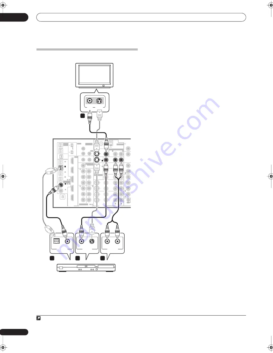
Connecting your TV and DVD player


The diagram shows a basic setup of this receiver together 
with a TV and DVD player, with S-video or composite 
video connections. Different TVs and DVD players may 
offer alternative connections. See also 


Using the 

component video jacks


 on page 14 if your TV and/or DVD 

player has component video inputs/outputs. If your DVD 
player offers multichannel analog audio outputs, see 


Connecting the multichannel analog inputs


 on page 54.


1

Connect the MONITOR OUT video jack to a video 

input on your TV.


Use a standard RCA/phono jack video cable to connect to 
the composite video jack, or for higher quality video, use 
an S-video cable to connect to the S-video jack.


2

Connect a composite or S-video output on your DVD 

player to the 


DVD/LD


 VIDEO or 


DVD/LD


 S-VIDEO input.


Connect using a standard video cable or an S-video 
cable.


3

Connect a coaxial-type


1


 digital audio output on 

your DVD player to the DIGITAL 1 (


DVD/LD


) input.


Use a coaxial cable designed for digital audio.


4

Connect the stereo audio outputs on your DVD 

player to the 


DVD/LD


 AUDIO inputs.


Connect using a stereo RCA/phono jack cable.

• If your DVD player has multichannel analog outputs, 

you can connect these instead. See also 


Connecting 

the multichannel analog inputs


 on page 54.

MULTI-ROOM
& SOURCE
/ REC SEL

ROOM3
(ZONE3)

OUT1

OUT2

USB
AUDIO
IN

S400

(AUDIO)

S400

(DVD/LD)
(TV)

FM UNBAL 75 Ω

AM LOOP

MONITOR

OUT

OUT

CD

CD-R/

TAPE

DVD/

LD

TV

SAT

VIDEO /
GAME1

OUT

DVR/

  VCR 1

DVR/

  VCR 2

OUT

IN

IN

VIDEO

VIDEO

AUDIO

S - VIDEO

IN

IN

IN

FR

F

SUB W.

SUR-

ROUND

SURR

CONTROL

OUT

PHONO

IN

IN

IN

IN

Y

P

B

P

R

Y

P

B

P

R

Y

P

B

P

R

Y

P

B

P

R

DIGITAL

COMPONENT VIDEO

ASSIGNABLE

ASSIGNA-

BLE

ASSIGNABLE

OUT

OUT

ANTENNA

MULTI-ROOM & SOURCE

AUDIO

IN

IN1

IN2

IN1

1

12 V  TRIGGER

2

MONITOR

OUT

MULTI-ROOM

& SOURCE

ROOM2

ROOM2(ZONE2)

ROOM2(ZONE2)

MAIN ROOM(ZONE1)

(ZONE2)

IN2

(DC OUT 12V TOTAL 50 mA MAX)

IN3

IN4

OUT

(SAT)

(DVR/

 VCR 1)

1

IN

2

(DVR/

 VCR 2)

IN

3

(DVD/

LD)

IN

1

(CD)

IN

IN

XM

2

IN

2

IN

OUT

1

IN

1

IN

2

IN

1

IN

2

R

L

HDMI

MULTI-ROOM

& SOURCE

IR

IN

3

(CD-R)

IN

4

4

1

2

1

2

1

3

1

R

L

R

R

R

TV

VIDEO

IN

S-VIDEO

IN

S-VIDEO

OPTICAL

DIGITAL OUT

VIDEO OUT

COAXIAL

DVD player

AUDIO

R

L

ANALOG OUT

VSX-84TXSi

3

1

2

4

Note


1 If your DVD player only has an optical digital output, you can connect it to one of the optical inputs on this receiver using an optical cable. When you set 
up the receiver you’ll need to tell the receiver which input you connected the player to (see 


The Input Setup menu


 on page 63).

VSX_84TXSi.book.fm 12 ページ 2006年3月13日 月曜日 午前11時54分

Summary of Contents for VSX 82TXS - AV Receiver

Page 1: ...AUDIO VIDEO MULTI CHANNEL RECEIVER VSX 84TXSi VSX 84TXSi S VSX 82TXS VSX 82TXS S Operating Instructions Register your product at www pioneerelectronics com US www pioneerelectronics ca Canada ...

Page 2: ... D8 10 2_En CAUTION This product satisfies FCC regulations when shielded cables and connectors are used to connect the unit to other equipment To prevent electromagnetic interference with electric appliances such as radios and televisions use shielded cables and connectors for connections D8 10 3a_En CAUTION TO PREVENT ELECTRIC SHOCK DO NOT USE THIS POLARIZED PLUG WITH AN EXTENSION CORD RECEPTACLE...

Page 3: ...grounding of the mast and supporting structure grounding of the lead in wire to an antenna discharge unit size of grounding conductors location of antenna discharge unit connection to grounding electrodes and requirements for the grounding electrode See Figure A LIGHTNING For added protection for this product during a lightning storm or when it is left unattended and unused for long periods of tim...

Page 4: ...05 Listening to your system Auto playback 27 Listening in surround sound 27 Standard surround sound 27 Using the Home THX modes 28 Using the Advanced surround effects 28 Listening in stereo 29 Using Stream Direct 29 Selecting MCACC presets 29 Choosing the input signal 30 Using surround back channel processing 30 Using the Virtual Surround Back mode 30 Using the Sound Retriever 31 06 Using the tune...

Page 5: ... 69 Default system settings 69 11 Controlling the rest of your system Setting the remote to control other components 71 Selecting preset codes directly 71 Programming signals from other remote controls 71 Erasing one of the remote control button settings 72 Resetting the remote control presets 72 Confirming preset codes 72 Renaming input source names 73 Direct function 73 Multi Operation and Syste...

Page 6: ...ns and do not operate the equipment on thick carpet or a bed Installing the receiver When installing this unit make sure to put it on a level and stable surface Don t install it on the following places on a color TV the screen may distort near a cassette deck or close to a device that gives off a magnetic field This may interfere with the sound in direct sunlight in damp or wet areas in extremely ...

Page 7: ...your DVD player your subwoofer and the TV Make sure you ve set the video input on your TV to this receiver Check the manual that came with the TV if you don t know how to do this Set the subwoofer volume to a comfortable level 4 Use the on screen automatic MCACC setup to set up your system See Automatically setting up for surround sound MCACC below for more on this 5 Play a DVD and adjust the volu...

Page 8: ...ttings manually using the System Setup menu starting on page 34 8 Note 1 You can t use the System Setup menu when the iPod or XM Radio input source is selected in either the main or sub room 2 If you cancel the Auto MCACC Setup or leave an error message for over three minutes the screen saver will appear 3 If you are planning on bi amping your front speakers or setting up a separate speaker system...

Page 9: ...ase Control technology provides coherent sound reproduction through the use of phase matching4 for an optimal sound image at your listening position The default setting is on and we recommend leaving Phase Control switched on for all sound sources Press PHASE PHASE CONTROL to switch on phase correction The PHASE CONTROL indicator on the front panel lights Note 1 Make sure that the TV s video input...

Page 10: ...ote control sensor for use in a multi room setup for example Connecting an IR receiver on page 59 8 12V trigger jacks total 50 mA max x2 Use to switch components in your system on and off according to the input function of the receiver Switching components on and off using the 12 volt trigger on page 60 9 Multi room and source outputs Use to connect a second amplifier in a separate room Multi room...

Page 11: ... page 47 19 RS 232C connector Use for connection to a PC for graphical output when using Advanced MCACC Connecting a PC for Advanced MCACC output on page 62 20 Speaker terminals Use for connection to the main front center surround and surround back speakers Installing your speaker system on page 17 21 Switched AC power outlet 100 W 0 8 A max Use to power another component in the system Power to th...

Page 12: ... a stereo RCA phono jack cable If your DVD player has multichannel analog outputs you can connect these instead See also Connecting the multichannel analog inputs on page 54 MULTI ROOM SOURCE RECSEL ROOM3 ZONE3 OUT1 OUT2 USB AUDIO IN S400 AUDIO S400 DVD LD TV FM UNBAL 75 Ω AM LOOP MONITOR OUT OUT CD CD R TAPE DVD LD TV SAT VIDEO GAME1 OUT DVR VCR 1 DVR VCR 2 OUT IN IN VIDEO VIDEO AUDIO S VIDEO IN ...

Page 13: ...r doesn t have a digital audio output you can skip this step MULTI ROOM SOURCE RECSEL ROOM3 ZONE3 OUT1 OUT2 USB AUDIO IN S400 AUDIO S400 DVD LD TV FM UNBAL 75 Ω AM LOOP MONITOR OUT OUT CD CD R TAPE DVD LD TV SAT VIDEO GAME1 OUT DVR VCR 1 DVR VCR 2 OUT IN IN VIDEO VIDEO AUDIO S VIDEO IN IN IN FR F SUB W SUR ROUND SURR CONTROL OUT PHONO IN IN IN IN Y PB PR Y PB PR Y PB PR Y PB PR DIGITAL COMPONENT V...

Page 14: ...ee way component video cable Note 1 In order to record you must connect the analog audio cables the digital connection is for playback only If your video component doesn t have a digital audio output you can skip this step 2 If your recorder only has a coaxial digital output you can connect it to one of the coaxial inputs on this receiver using a coaxial digital audio cable When you set up the rec...

Page 15: ...ROUND BACK CONTROL OUT PHONO IN IN IN IN Y PB PR Y PB PR Y PB PR Y PB PR DIGITAL COMPONENT VIDEO ASSIGNABLE ASSIGNA BLE ASSIGNABLE OUT OUT ANTENNA MULTI ROOM SOURCE AUDIO IN IN1 IN2 IN1 1 12 V TRIGGER 2 MONITOR OUT MULTI ROOM SOURCE ROOM2 ROOM2 ZONE2 ROOM2 ZONE2 MAIN ROOM ZONE1 ZONE2 IN2 DC OUT12VTOTAL50 mAMAX IN3 IN4 OUT SAT DVR VCR 1 1 IN 2 DVR VCR 2 IN 3 DVD LD IN 1 CD IN IN XM 2 IN 2 IN OUT 1 ...

Page 16: ...ack VIDEO an S Video jack S VIDEO stereo analog audio inputs AUDIO L R and an optical digital audio input DIGITAL You can use these connections for any kind of audio video component but they are especially convenient for portable equipment such as camcorders video games and portable audio video equipment Select these inputs using INPUT SELECT remote or the INPUT SELECTOR dial front panel to select...

Page 17: ...RONT CENTER SUR ROUND SWITCHED 100 W 0 8A MAX FRONT R L R L R L Single CENTER SURROUND SURROUND BACK Single SUR ROUND BACK OUT PHONO IN IN IN IN Y PB PR Y PB PR Y PB PR Y PB PR DIGITAL COMPONENT VIDEO ASSIGNABLE ASSIGNA BLE ASSIGNABLE OUT IN OUT ANTENNA MULTI ROOM SOURCE AUDIO PRE OUT IN IN1 IN2 IN1 1 12 V TRIGGER 2 MONITOR OUT MULTI ROOM SOURCE ROOM2 ROOM2 ZONE2 ROOM2 ZONE2 MAIN ROOM ZONE1 ZONE2 ...

Page 18: ... near the TV we recommend using magnetically shielded speakers to prevent possible interference such as discoloration of the picture when the TV is switched on If you do not have magnetically shielded speakers and notice discoloration of the TV picture move the speakers farther away from the TV If you re using a center speaker place the front speakers at a wider angle If not place them at a narrow...

Page 19: ...Before fixing make sure that the reception is satisfactory 2 Pull off the protective shields of both AM antenna wires 3 Press the AM LOOP antenna terminal tabs to open and insert one wire into each terminal 4 Release the tabs to secure the AM antenna wires 5 Place the AM antenna on a flat surface and point in the direction giving the best reception Avoid placing near computers television sets or o...

Page 20: ...not in the cord or tie it with other cables The power cords should be routed so that they are not likely to be stepped on A damaged power cord can cause a fire or give you an electric shock Check the power cord once in a while If you find it damaged ask your nearest Pioneer authorized independent service company for a replacement The receiver should be disconnected by removing the mains plug from ...

Page 21: ... HDMI indicator Blinks when connecting an HDMI equipped component lights when the component is connected page 50 7 Digital Precision Processing indicator Lights to indicate digital processing for example it disappears when Pure Direct page 29 is on or when listening through the multichannel analog inputs 8 Character display See Display on page 23 SPEAKERS TUNE ENTER TUNE PHONES AV PARAMETER SETUP ...

Page 22: ... on page 59 You will also need to use the REC SEL controls when recording a source see Making an audio or a video recording on page 67 19 VIDEO SELECT Press repeatedly to select the video source page 68 20 SIGNAL SELECT Use to select an input signal page 30 21 SBch PROCESSING Selects the surround back channel mode page 30 or virtual surround back mode page 30 22 STEREO Switches to stereo playback ...

Page 23: ...o mode MONO Lights when the mono mode is set using the MPX button 10 Master volume level Shows the overall volume level 80dB indicates the minimum level and 12dB indicates the maximum level 11 Input source indicators Light to indicate the input source you have selected 12 STREAM DIRECT Lights when Direct Pure Direct is selected page 29 13 Speaker indicators Lights to indicate the current speaker s...

Page 24: ...directly using the number buttons page 32 CLASS Switches between the three banks classes of radio station presets page 33 5 Tuner component control buttons SETUP These button controls can be accessed after you have selected the corresponding input source button DVD DVR1 SAT etc The BAND and T EDIT tuner controls are explained on page 32 and page 33 Press RECEIVER first to access the following cont...

Page 25: ...e to control other components see Controlling the rest of your system on page 71 SETUP Indicates the setup mode from which you choose the options below PRESET See Selecting preset codes directly on page 71 LEARNING See Programming signals from other remote controls on page 71 MULTI OP See Multi Operation and System Off on page 73 SYS OFF See Multi Operation and System Off on page 73 DIRECT F See D...

Page 26: ...ge 49 Selects the shuffle mode of an iPod page 47 6 DISP Switches between named station presets and radio frequencies page 33 7 Component control buttons These are used to control a component after you have selected it using the input source buttons 8 MUTE Mutes the sound or restores the sound if it has been muted adjusting the volume also restores the sound 9 Multi room select Selects the room yo...

Page 27: ...With two channel sources you can select from 2 Pro Logic IIx MOVIE Up to 7 1 channel sound especially suited to movie sources 2 Pro Logic IIx MUSIC Up to 7 1 channel sound especially suited to music sources5 2 Pro Logic IIx GAME Up to 7 1 channel sound especially suited to video games 2 PRO LOGIC 4 1 channel surround sound sound from the surround speakers is mono Neo 6 CINEMA 6 1 channel sound esp...

Page 28: ...m the output of a video game console Using the Advanced surround effects The Advanced surround effects can be used for a variety of additional surround sound effects Most Advanced Surround modes are designed to be used with film soundtracks but some modes are also suited for music sources Try different settings with various soundtracks to see which you like Press ADV SURR ADVANCED SURROUND repeate...

Page 29: ...ls in the signal PURE DIRECT Analog and PCM sources are heard without any digital processing 1 No sound is output from the Second Zone in this mode Selecting MCACC presets Default setting MEMORY 1 If you have calibrated your system for different listening positions2 you can switch between settings to suit the kind of source you re listening to and where you re sitting for example watching movies f...

Page 30: ...s better in the format for example 5 1 for which it was originally encoded you can have the receiver only apply this effect to 6 1 encoded sources like Dolby Digital EX or DTS ES 4 The table indicates when you will hear the virtual surround back channel Virtual surround back channel is active Press SBch SBch PROCESSING repeatedly to cycle the virtual surround back channel options Each press cycles...

Page 31: ...he sound retriever on or off Type of source SBch Processing Virtual SB mode Standard THX Advanced surround Multichannel sources Stereo sources 2 Pro Logic II x 2 Pro Logic Neo 6 Dolby Digital EX DTS ES encoded multichannel sources with 6 1ch surround ON AUTO Dolby Digital DTS WMA9 Pro encoded DVD Audio and SACD multichannel sources ON AUTO Dolby Digital DTS PCM WMA9 Pro encoded DVD Audio and SACD ...

Page 32: ...hen tuning to an FM station because the signal is weak press the MPX button to switch the receiver into mono reception mode This should improve the sound quality and allow you to enjoy the broadcast Tuning directly to a station Sometimes you ll already know the frequency of the station you want to listen to In this case you can simply enter the frequency directly using the number buttons on the re...

Page 33: ... name up to four characters long ABCDEFGHIJKLMNOPQRSTUVWXYZ abcdefghijklmnopqrstuvwxyz 0123456789 _ Use the ST buttons remote to select characters Press ENTER to confirm a character If no character is input a space is input The name is stored when ENTER is pressed after choosing the fourth character Tip To erase a station name simply repeat steps 1 3 and input four spaces instead of a name Once yo...

Page 34: ...CACC Expert If your setup requires more detailed settings than those provided in Automatically setting up for surround sound MCACC on page 7 you can customize your setup options below You can calibrate your system differently for up to six different MCACC presets3 which are useful if you have different listening positions depending on the type of source for example watching movies from a sofa or p...

Page 35: ...he microphone is connected If you re using a subwoofer it is automatically detected every time you switch on the system Make sure it is on and the volume is turned up See Problems when using the Auto MCACC Setup on page 9 for notes regarding high background noise levels and other possible interference 5 Wait for the Auto MCACC Setup to finish outputting test tones A progress report is displayed on...

Page 36: ...r more on this Speaker Distance The distance of your speakers from the listening position see page 45 for more on this 3 Standing Wave Filter settings to control lower boomy frequencies see page 38 for more on this Acoustic Cal EQ Adjustments to the frequency balance of your speaker system based on the acoustic characteristics of your room see page 39 for more on this Press ENTER after you have fi...

Page 37: ... notes regarding high background noise levels and other possible interference If you re using a subwoofer switch it on and turn up the volume to the middle position 1 Select Manual MCACC from the System Setup menu See Making receiver settings from the System Setup menu on page 34 if you re not already at this screen 2 Select the setting you want to adjust If you re doing this for the first time yo...

Page 38: ...stretched pointing at each speaker Try to make the two tones sound as if they are arriving simultaneously at a position slightly in front of you and between your arm span 1 When it sounds like the delay settings are matched up press to confirm and continue to the next channel For comparison purposes the reference speaker will change depending on which speaker you select If you want to go back and ...

Page 39: ...ing Use the buttons to select the channel Use the buttons to select the frequency and to boost or cut the EQ When you re finished go back to the top of the screen and use the buttons to select the next channel The OVER indicator shows in the display if the frequency adjustment is too drastic and might distort If this happens bring the level down until OVER disappears from the display Tip Changing ...

Page 40: ...ration and professional calibration the gray circles represent the point at which the microphone captures the sound for frequency analysis As soon as audio is output from your speaker system it is influenced by room characteristics such as walls furniture and the dimensions of the room The sooner the frequency analysis the less it is influenced by the room We recommend an earlier time setting of 2...

Page 41: ... to check Use the buttons to go back and forth between the two Note that the markers on the vertical axis indicate decibels in 2 dB steps 5 If you selected Advanced EQ Setup input the time setting you want to use for calibration then select Go Select Start from the next screen Based on the reverb measurement above you can choose the time period that will be used for the final frequency adjustment ...

Page 42: ... menu Copying MCACC preset data If you want to manually adjust the Acoustic Calibration EQ see Manual MCACC setup above we recommend copying your current settings2 to an unused MCACC preset Instead of just a flat EQ curve this will give you a reference point from which to start 1 Select MCACC Data Copy from the Data Management setup menu 2 Select the MCACC preset you ll be copying the settings Fro...

Page 43: ...tings in order Speaker Setting Specify the size and number of speakers you ve connected see below Channel Level Adjust the overall balance of your speaker system page 44 Speaker Distance Specify the distance of your speakers from the listening position page 45 Bass Peak Level Prevent bass tones from distorting the sound from your speakers page 45 X Curve Adjust the tonal balance of your speaker sy...

Page 44: ...r automatically 3 Confirm your selected setup option The test tones will start after you press ENTER 4 Adjust the level of each channel using the buttons If you selected Manual use to switch speakers The Auto setup will output test tones in the order shown on screen Adjust the level of each speaker as the test tone is emitted 5 5 When you re finished press RETURN You will return to the Manual SP S...

Page 45: ...ut is not affected 2 Select a setup option Setting Start The volume is set to 60 dB a test tone plays back and you make the setting Setting Clear Clears any previous setting and switches limiting off 3 If you selected Setting Start use to adjust the test tones and specify the bass peak level then press ENTER 5 If you are using a Sound Pressure Level SPL meter take the readings from your main liste...

Page 46: ...m see About THX on page 85 it is required that you make the setting See Placing the speakers on page 18 for more on THX speaker placement 3 1 Select THX Audio Setting from the Manual SP Setup menu 2 Specify the distance of your surround back speakers from each other 0 1 ft Surround speakers within 1 foot apart best for THX surround sound 1 4 ft Surround speakers between 1 and 4 feet apart 4 ft Sur...

Page 47: ...to browse that category To return to the previous level press RETURN Note 1 This system is compatible with an iPod iPod mini and iPod Photo portable device third generation and above however compatibility may vary depend ing on the software version of your iPod This receiver does not support software versions prior to iPod update 2004 10 20 For supported versions consult your local Pioneer dealer ...

Page 48: ...art playback If you start playback when something other than a song is selected all the songs that fall into that cat egory will play Press to stop playback Pauses playback or restarts playback when paused Press and hold during playback to start scanning Press to skip to previous next song Press repeatedly to switch between Repeat One Repeat All and Repeat Off Press repeatedly to switch between Sh...

Page 49: ...s been adopted by XM Satellite Radio for digital radio broadcasts of surround recordings and live events Neural Surround employs psychoacoustic frequency domain processing which allows delivery of a more detailed sound stage with superior localization of surround elements System playback is scalable from stereo up to state of the art multichannel surround Neural Surround is trademark owned by Neur...

Page 50: ... to connect on of the HDMI IN interconnects on this receiver to an HDMI output on your HDMI component HDMI appears on the front panel when an HDMI equipped component is connected Note 1 An HDMI connection can only be made with DVI equipped components compatible with both DVI and High Bandwidth Digital Content Protection HDCP If you choose to connect to a DVI connector you will need a separate adap...

Page 51: ...dwidth of up to 2 2 gigabytes per second with HDTV signals one connector instead of several cables and connectors and communication between the AV source and AV devices such as DTVs HDMI the logo and High Definition Multi media Interface are trademarks or registered trademarks of HDMI licensing LLC Using the i LINK interface VSX 84TXSi only If you have a component with an i LINK connector you can ...

Page 52: ... i LINK If a connected devices cannot output playback a source using the i LINK connection is displayed after the input device name e g DV 79AVi Non compatible devices cannot be assigned to inputs When the cables for an assigned input device become loose or the power is cut to the device an asterisk appears before the device name e g DV 79AVi CD 3 When you re finished press RETURN You will return ...

Page 53: ...ation This receiver is DTCP Digital Transmission Content Protection compliant so you can play DVD A DVD Video and SACD i LINK audio When setting up an i LINK network it s important that the components form an open ended chain fig 1 or a tree fig 2 The system will not work if the connected components form a loop If a loop is detected the message LOOP CONNECT shows in the display Figs 3 and 4 show c...

Page 54: ...INPUT see Selecting the multichannel analog inputs above for more on this 2 When playback from the multichannel inputs is selected you can t use Midnight Loudness Dialog Enhancement or the SIGNAL SELECT and ANA LOG ATT buttons as well as any of the listening modes including STEREO and the surround back channel processing When playback from the multichannel inputs is selected only the volume and ch...

Page 55: ...ce between 6 Ω to 16 Ω please see Switching the speaker impedance on page 68 if you plan to use speakers with an impedance of less than 8 Ω After selecting 2nd Zone in Surround back speaker setting on page 36 you can use the speakers connected to the surround back B speaker terminals on the rear panel to listen to stereo playback in another room See Switching the speaker system below for the liste...

Page 56: ...s output the same audio it doesn t matter which set front or surround back is powering which part High or Low of the speaker Make sure that the connections are properly inserted 2 Select the Front Bi Amp setting from the Surr Back System menu See Surround back speaker setting on page 36 to specify how you re using the surround back speaker terminals Caution Most speakers with both High and Low ter...

Page 57: ... Surround back channel amplifier INPUT ANALOG Powered subwoofer INPUT ANALOG Center channel amplifier mono Note 1 You can t use sound controls such as the tone controls or Midnight listening or any surround modes with a separate amplifier in the sub room You can however use the features available with your sub room amplifier MULTI ROOM SOURCE RECSEL ROOM3 ZONE3 OUT1 OUT2 USB AUDIO IN S400 AUDIO S4...

Page 58: ... IN 1 IN 2 IN 1 IN 2 R L HDMI MULTI ROOM SOURCE IR IN 3 CD R IN 4 4 1 2 1 2 1 3 1 R L R R R Sub room Main room S400 AUDIO S400 DVD LD TV FM UNBAL 75 Ω AM LOOP MONITOR OUT OUT CD CD R TAPE DVD LD TV SAT IN IN IN FR FL OUT PHONO IN IN IN Y Y ASSIGNABLE OUT MULTI ROOM SOURCE IN1 IN2 IN1 1 12 V TRIGGER 2 MONITOR OUT MULTI ROOM SOURCE ROOM2 ROOM2 ZONE2 ROOM2 ZONE2 MAIN ROOM ZONE1 ZONE2 IN2 DC OUT12VTOT...

Page 59: ...s or Xantech unit to control your system instead of the remote sensor on the front panel of this receiver 6 Note 1 Note that when recording this also selects the RECOUT input source See Making an audio or a video recording on page 67 for more on this 2 If the receiver is in standby the display is dimmed and ZONE and your selected sub room s continue to show in the display SPEAKERS TUNE ENTER TUNE ...

Page 60: ...O VIDEO AUDIO S VIDEO IN IN IN FR FL SUB W CENTER MULTI CH IN SPEAKERS RS 232C SUR ROUND SURROUND BACK CONTROL iPod SUBW FRONT CENTER SUR ROUND FRONT R L Single SUR ROUND BACK OUT PHONO IN IN IN IN Y PB PR Y PB PR Y PB PR Y PB PR DIGITAL COMPONENT VIDEO ASSIGNABLE ASSIGNA BLE ASSIGNABLE OUT IN OUT ANTENNA MULTI ROOM SOURCE AUDIO PRE OUT IN IN1 IN2 IN1 1 12 V TRIGGER 2 MONITOR OUT MULTI ROOM SOURCE...

Page 61: ...e Automatic video input switching on the plasma display Automatic volume muting on the plasma display See also SR Setup for Pioneer plasma displays on page 65 for more on setting up the receiver Important The additional SR features do not work when the iPod or XM Radio functions are selected 1 Make sure that the plasma display and this receiver are switched on and that they are connected with the ...

Page 62: ...ower outlet when you do this 1 Use a commercially available cable to connect the RS 232C jack on your computer to the 9 pin RS 232C jack on this receiver See the documentation provided with the Advanced MCACC application for more information Advanced MCACC output using your PC Before continuing make sure you have completed steps 1 3 in Professional Acoustic Calibration EQ on page 39 Note that tran...

Page 63: ...hecking the i LINK inputs on page 52 2 6 When you re finished select Next to continue to the next screen The second screen of the Input setup has three optional settings Input name You can choose to rename the input function for easier identification Select Rename to do so or Default to return to the system default SLEEP ANALOG VIDEO RECEIVER SOURCE SYSTEM OFF INPUT SELECT DVD SAT VIDEO1 TVCONT DV...

Page 64: ...tting for a multi room setup see Multi Room Setup below SR Setup Specify how you want to control your Pioneer plasma display see SR Setup for Pioneer plasma displays below OSD Adjustment Adjust the position of the on screen display on your TV see OSD Adjustment below iLINK Check VSX 84TXSi only Check which i LINK equipped components you have connected and which input function they are assigned to ...

Page 65: ... does not control the volume of the plasma display ON When the receiver is switched to one of the inputs that use the plasma display DVD LD for example the volume on the plasma display is muted so only sound from the receiver is heard 3 Assign any input source connected to the plasma display to the corresponding input number This matches the receiver s input source with a numbered video input on t...

Page 66: ...ts the center image to create a wider stereo effect with vocals Adjust the effect from 0 all center channel sent to front right and left speakers to 10 center channel sent to the center speaker only 0 to 10 Default 3 Effect Sets the effect level for the currently selected Advanced Surround mode each mode can be set separately 10 to 90 High Bit High Sampling Creates a wider dynamic range with digit...

Page 67: ...ource you re currently listening to as in Making an audio or a video recording above Contrast Adjusts the contrast between light and dark 10 to 10 Default 0 Hue Adjusts the red green balance 10 to 10 Default 0 Resolutione Specifies the output resolution of the video signal select this according to the resolution of your monitor and the disc you wish to watch PURE 480p 720p 1080i Aspect Specifies t...

Page 68: ...e sleep timer Press SLEEP repeatedly to set the sleep time You can check the remaining sleep time at any time by pressing SLEEP once Pressing repeatedly will cycle through the sleep options again 4 Dimming the display You can choose between four brightness levels for the front panel display Note that when selecting sources the display automatically brightens for a few seconds Press DIMMER repeated...

Page 69: ...ver is unplugged Default system settings Note 1 If the Pure Direct mode is switched on some settings above will show OFF even though they are on Input source Listening mode Signal select Surround Back Processing Sound Retriever Video Select MCACC Position Room 2 REC SEL Room 3 SHIFT STATUS MCACC S DIRECT MULTI OPE SIGNAL SEL PHOTO SBch STEREO AUDIO SUBTITLE ADV SURR STANDARD PHASE THX HDD CH CH DV...

Page 70: ...TO SURROUND Listening Mode x ch AUTO SURROUND Listening Mode HP STEREO See also Setting the AV options on page 66 for other default DSP settings MCACC Channel level M1 M6 0 dB Speaker Distance M1 M6 10 ft Standing Wave M1 M6 Standing Wave On Off ON ATT 0 dB SWch Wide Trim 0 0 EQ Data M1 M6 All channels bands 0 dB EQ Wide Trim M1 M6 0 0 dB Setting Default ...

Page 71: ...t on or off into standby by pressing SOURCE If it doesn t seem to work select the next code from the list if there is one If you can t find or properly enter a preset code you can still teach the remote individual commands from another remote control see Programming signals from other remote controls below 7 If your component is controlled successfully press ENTER to confirm The remote LCD display...

Page 72: ...te control presets This will erase all preset remote control preset codes and programmed buttons 1 While pressing the RECEIVER button press SETUP The remote LCD display shows SETUP 2 Use to select RESET then press ENTER RESET flashes in the LCD display 3 Press and hold ENTER for about two seconds The LCD shows OK to confirm the remote presets have been erased Confirming preset codes Use this featu...

Page 73: ...n of the input source you want to control 3 Press the input source button for the component you want to control then press ENTER 4 Use to switch direct function ON or OFF then press ENTER The LCD shows OK to confirm the setting Multi Operation and System Off The Multi Operation feature allows you to program a series of up to 5 commands for the components in your system For example you could turn o...

Page 74: ...tions You can start multi operations with the receiver switched on or in standby 1 Press MULTI OPE MULTI OP flashes in the display 2 Press an input source button that has been set up with a multi operation The receiver switches on if it was in standby and the programmed multi operation is performed automatically Using System off 1 Press MULTI OPE MULTI OP flashes in the display 2 Press SOURCE The ...

Page 75: ...ing Cable TV Satellite TV TV DTV RETURN Use to select RETURN or EXIT DTV Number buttons Use to select a specific TV channel Cable TV Satellite TV TV DTV 10 button Use to add a decimal point when selecting a specific TV channel DTV ENTER DISC Use to enter a channel Cable TV Satellite TV TV DTV MENU Select different menus from the DTV functions DTV Select the menu screen Cable TV Satellite TV TV ENT...

Page 76: ... DVR player AUDIO Changes the audio language or channel DVD DVR player SUBTITLE Displays changes the subtitles on multilingual DVDs DVD DVR player SHIFT SUBTITLE Switches to the VCR controls when using a VCR DVD HDD recorder VCR DVD DVR player HDD SHIFT CH Switches to the hard disk controls when using a DVD HDD recorder DVR player DVD SHIFT CH Switches to the DVD controls when using a DVD HDD reco...

Page 77: ... then back on again Try disconnecting the power cable then connect again AMP ERR blinks in the display then the power automatically switches off The MCACC blinks and the power does not turn on The receiver may have a serious problem Do not try switching the receiver on Contact a Pioneer authorized independent service company for help FAN STOP blinks in the display then the power automatically swit...

Page 78: ...e Channel Level on page 44 Check that the speaker hasn t been set to NO see Speaker Setting on page 43 The channel may not be recorded in the source By using one of the advanced effect listening mode you may be able to create the missing channel see Listening in surround sound on page 27 Sound is produced from analog components but not from digital ones DVD LD CD ROM etc Check that the input signa...

Page 79: ...nal computers or other digital components connected to the same power source are not causing interference There seems to be a time lag between the speakers and the output of the subwoofer See Automatically setting up for surround sound MCACC on page 7 to set up your system again using MCACC this will automatically compensate for a delay in the subwoofer output The maximum volume available shown in...

Page 80: ... no adjustment needed The graph may appear to have shifted vertically when comparing before and after measurements EQ adjustments made using the Manual MCACC setup on page 37 do not appear to change the graphical output Despite level adjustments being made the filters used for analysis may not display these adjustments in the graphical output However these adjustments are taken this into account b...

Page 81: ...mote control see Loading the batteries on page 6 Be sure to operate within 23 feet and a 30º angle of the remote sensor on the front panel see Operating range of remote control unit on page 22 Check that there are no obstacles between the receiver and the remote control Make sure that there is no fluorescent or other strong light shining on to the remote sensor Check the connections of the CONTROL...

Page 82: ...ved from the network The sound may be interrupted if this happens during playback LOOP CONNECT The i LINK network cannot function because the connected components form a loop See Creating an i LINK network on page 53 for more on this NO NAME When an i LINK equipped component has no name this message is displayed instead of the proper component name NO SIGNAL A component is outputting an i LINK sig...

Page 83: ... still persists when connecting your HDMI component directly to your monitor please consult the component or monitor manual or contact the manufacturer for support Symptom Remedy Symptom Cause Action Error I1 There is a problem with the signal path from the iPod to the receiver Switch off the receiver and reconnect the iPod to the receiver If this doesn t seem to work try resetting your iPod Error...

Page 84: ...m which embeds surround sound information within a stereo soundtrack which a Dolby Pro Logic decoder can then use for enhanced surround listening with greater sound detail Manufactured under license from Dolby Laboratories Dolby Pro Logic Surround EX and the double D symbol are trademarks of Dolby Laboratories DTS The DTS technologies are explained below See www dtstech com for more detailed infor...

Page 85: ...ct2 Before any home theatre component can be THX Select2 certified it must incorporate all the features above and also pass a rigorous series of quality and performance tests Only then can a product feature the THX Select2 logo which is your guarantee that the Home Theatre products you purchase will give you superb performance for many years to come THX Select2 requirements cover every aspect of t...

Page 86: ...s outline the listening modes available with different input signal formats depending on the surround back channel processing and decoding method you have selected Stereo 2 channel signal formats SBch Processing Input signal format Standard THX Auto Surround SBch Processing ON AUTO Automatically selects 6 1 7 1 channel decoding Dolby Digital Surround 2 Pro Logic IIx MOVIE 2 Pro Logic IIx MUSIC 2 P...

Page 87: ...ital EX 2 Pro Logic IIx MOVIEa 2 Pro Logic IIx MUSIC THX MUSICMODEa Dolby Digital EX 2 Pro Logic IIx MOVIEa SBch Processing AUTO Automatically selects 6 1 7 1 channel decoding WMA9 Pro 6 1 7 1 channel Straight decoding WMA THX CINEMA Straight decoding Dolby Digital EX 6 1 channel flagged Dolby Digital EX 2 Pro Logic IIx MOVIEa THX SURROUND EX Dolby Digital EX 2 Pro Logic IIx MOVIEa DTS ES 6 1 chan...

Page 88: ...rces As above PCM DIRECT stereo SACD sourcesa As above SACD DIRECT stereo a VSX 82TXS only SACD DIRECT is automatically selected with SACD sources Surround Back speaker s Input signal format DIRECT PURE DIRECT Connected Maximum 7 1 channel playback WMA9 Pro 6 1 7 1 channel Straight decoding Straight decoding Dolby Digital EX 6 1 channel flagged Dolby Digital EX 2 Pro Logic IIx MOVIEa Dolby Digital...

Page 89: ...Impedance 1 Vp p 75 Ω Signal to Noise Ratio 65 dB Frequency Response 5 Hz to 100 MHz FM Tuner Section Frequency Range 87 5 MHz to 108 MHz Usable Sensitivity Mono 13 2 dBf IHF 1 3 µV 75 Ω 50 dB Quieting Sensitivity Mono 20 2 dBf Stereo 38 6 dBf Signal to Noise Ratio Mono 73 dB at 85 dBf Stereo 70 dB at 85 dBf Distortion Stereo 0 5 1 kHz Alternate Channel Selectivity 60 dB 400 kHz Stereo Separation ...

Page 90: ...The Phase Control technology incorporated into this receiver s design provides coherent sound reproduction through the use of phase matching for an optimal sound image at your listening position i LINK digital interface VSX 84TXSi only The i LINK interface makes it possible to connect this receiver to i LINK equipped components allowing you to enjoy high sampling rate up to 192 kHz PCM multichanne...

Page 91: ...able sound level Set the dial and leave it there Taking a minute to do this now will help to prevent hearing damage or loss in the future After all we want you listening for a lifetime We Want You Listening For A Lifetime Used wisely your new sound equipment will provide a lifetime of fun and enjoyment Since hearing damage from loud noise is often undetectable until it is too late this manufacture...

Page 92: ...ease do not ship your product to Pioneer without first calling the Customer Support Division at the above listed number for assistance Pioneer Electronics USA Inc Customer Support Division P O BOX 1760 Long Beach CA 90801 1760 U S A For warranty information please see the Limited Warranty sheet included with your product Should this product require service in Canada please contact a Pioneer Canadi...

Reviews: