background image

39

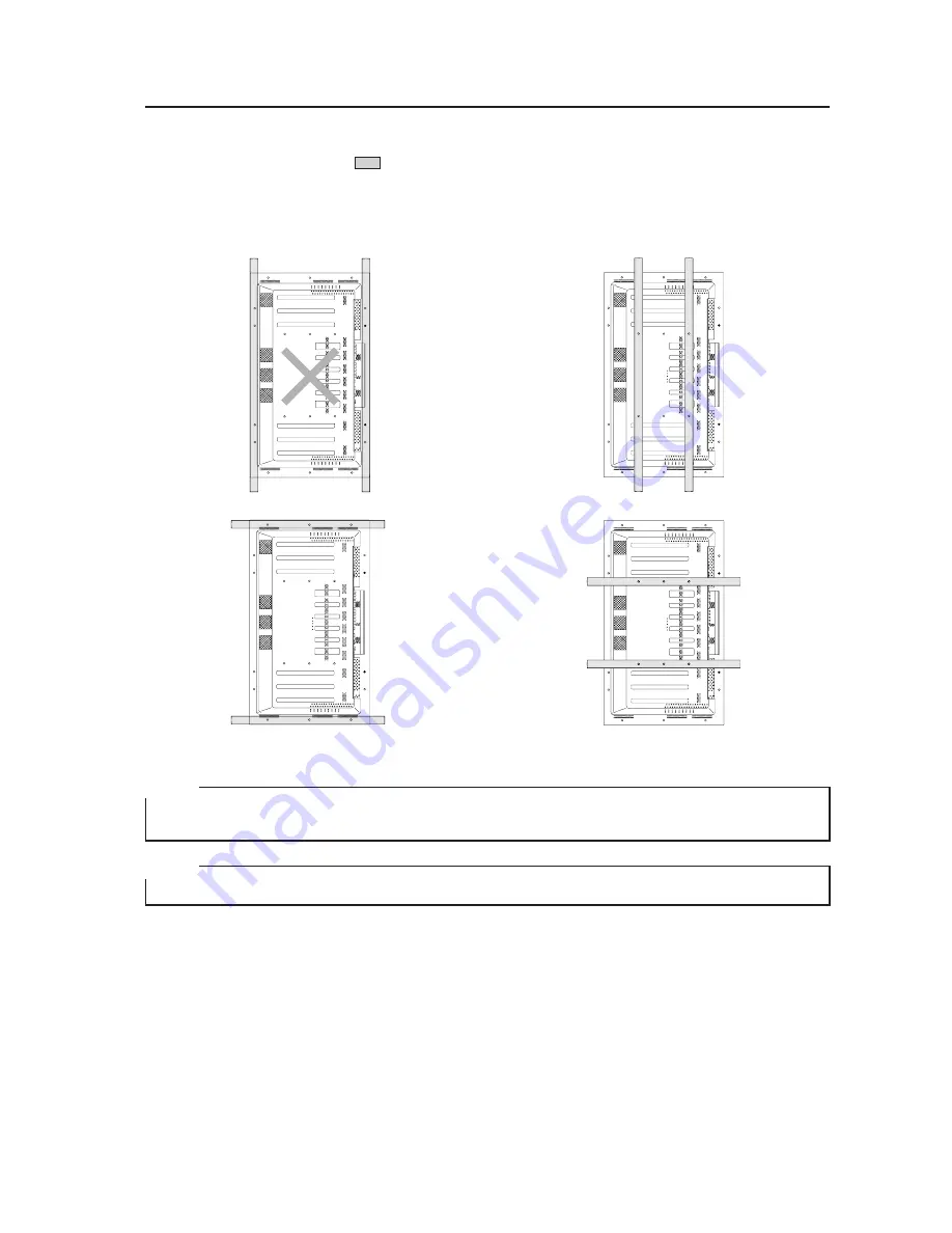
Special Installation (Hanging from the wall (lengthwise))

Methods of Securing: Basic methods of securing are shown below. Avoid blocking or covering areas aside from those

indicated by 

 . The method indicated by a large X-mark must not be used.

Before attaching the unit to fittings, double-check that the thickness and height of the fittings,

and the number of fixing bolts is correct.

(Also refer to 3.4.1 “Mounting to fittings”.)

NOTE 1

Heated air is drawn off from the interior of the unit by fans. Before installation, consider the heat resistance of the

wall or other surfaces behind the unit. Exhaust temperatures can be 30 °C higher than the outside temperature.

NOTE 2

For wall-mounting, do not bundle the cables in a way that will obstruct ventilation.

Summary of Contents for PDP 502MX

Page 1: ...rs PRECAUTIONS We accept no responsibility for losses resulting from the use of parts other than those supplied by us We guarantee the performance of our products only when they are assembled and adjusted as described in this manual The specifications and external designs shown in this manual are subject to change without notice CAUTION Exclamation marks placed within triangles are intended to ale...

Page 2: ... Specifications 51 4 4 2 Mount locations for floor fastening screws 52 4 4 3 Dimensions 52 4 4 4 Assembling the stand 53 4 4 5 Mounting to the main unit 54 4 5 Plasma Display Ceiling Suspension Hardware one side type PDK 5002 55 4 5 1 Specifications 55 4 5 2 External Dimensions 56 4 5 3 Assembling and Installing the mounting hardware and mounting the plasma display 57 4 6 PDP Bracket PDK 5005 61 4...

Page 3: ...28 5 4 6 SCREEN adjustment values area tables 130 5 5 RS 232C Adjustment Mode 131 5 5 1 About the RS 232C adjustment mode 131 5 5 2 Interface 132 5 5 3 ID assignment 133 5 5 4 List of RC 232C commands 134 5 5 5 About the GET commands 136 5 6 Combination Connection 138 5 6 1 Connections 138 5 7 KEY LOCK UNLOCK 140 5 7 1 Functions 140 5 7 2 How to switch KEY LOCK UNLOCK 140 5 8 Regarding the problem...

Page 4: ... compression or partial display UXGA requires display image compression For playback of HDTV signals TV broadcasts a separate DTV set top box is required Free choice of installation layout slim design Highly efficient heat dissipation design not only makes it possible to operate the display in a wider range of temperatures but also reduces the amount of ambient noise generated Can be installed in ...

Page 5: ...5 Features ...

Page 6: ...t Pin jack 2 for INPUT 1 2 L R above 500 mVrms 10 kΩ AUDIO INPUT Input Stereo mini jack 2 for INPUT 3 4 L R above 500 mVrms 10 kΩ AUDIO OUTPUT Output Stereo mini jack L R below the upper limit of 500 mVrms national 5 kΩ SPEAKER Output L R 8 to 16 Ω 2 W 2 W when 8 Ω Control related RS 232C terminal D sub 9 pin male Combination In Out Terminal Mini DIN 6 pin Control In Out Terminal Monaural mini jac...

Page 7: ...nals supported PC signals supported Caution These signals are tested to work correctly Other signal frequencies than listed may couse undesirable images Apple Macintosh 16 1376 x 768 Figure in brackets are for Apple Macintosh 19 56 4Hz 70 1Hz 60Hz 66 7Hz 72Hz 75Hz 85Hz 56Hz 60Hz 72Hz 75Hz 85Hz 640 x 400 640 x 480 800 x 600 Remark NEC PC 9800 NEC PC 9800 852 x 480 864 x 480 Apple Macintosh 13 1072 ...

Page 8: ...colors For packaging information refer to 3 3 2 Unpacking Center of gravity Unit mm External Dimensions 1162 104 590 104 150 150 250 250 660 2 M8 special screw for anchoring plain stand Rear View 496 18 M8 φ 16 mm with hole rivet 609 1218 1291 628 1128 357 Light sensor for the remote 98 65 MAIN POWER switch Centering Unit operating panel 714 31 4 Effective screen dimensions 1098 900 Terminal area ...

Page 9: ...9 Main Unit Operation Panel Light Sensor for the Remote External Dimensions 22 5 11 1 7 8 11 STANDBY ON INPUT MENU ADJUST SET SIZE DISPLAY 146 6 48 1 29 8 21 4 ...

Page 10: ...mini jack Used to output the sound from a device connected to the display to a device such as an AV amplifier Combination Input and Output Terminals Used for simultaneous control of various units Refer to 5 6 Combination Connection Please use a Mini DIN 6 pin cable straight all pins wire bound this is readily available on the market as the connector cable NOTE No ABL linkage function is provided T...

Page 11: ...unit take a total of five other units as the standard number that can be set to receive input from it However when inputting outputting to from separate sync or composite sync the source sync level at the end terminal must be 2 2 kΩ and over 4 8 Vp p INPUT 3 G Y B CB PB R CR PR Receives signals from RGB or video hardware NOTE Also supports Green on Sync HD H V SYNC Receives signals of HD and H V S...

Page 12: ...ut Remote control output 3 TxD output RxD input 4 NC not connected NC not connected 5 RxD input TxD output 6 NC not connected NC not connected 5 9 6 1 Combination IN OUT terminal pin layout 5 3 1 6 4 2 RS 232C terminal D sub 9 pin connector male pin layout Note Plasma communicates as a DCE derice Pin No INPUT4 input terminals INPUT4 output terminals 1 R or CR PR 2 G or Y 3 B or CB PB 4 NC not conn...

Page 13: ...d Adjustment buttons 5 32 Used to move the cursor on the menu screen or to adjust various settings INPUT button Used to select inputs SCREEN SIZE button Used to manually select the screen size SET select button Used to select the item to be adjusted on the menu screen Used to change the various settings MENU button Used to display the menu screen VOL buttons Used to adjust the volume DISPLAY DISPL...

Page 14: ...unit case and attach it to the rear of the main unit or some other fixed surface so that it will be available for putting away the remote control unit when it is not in use Remote control unit Upper and lower tape Example of remote control unit case attachment Remote control unit case NOTE Do not obstruct the air holes in the remote control unit case ...

Page 15: ...15 Remote Control Unit Case ...

Page 16: ...uch as hang bolts 4 Sufficient work space Select a location with sufficient space for installation work The installation work should be conducted by two or more persons 5 Nearby equipment If air conditioning ducts or lamps etc are located near the installation site the attendant dust extreme temperatures humidity and condensation may become sources of trouble Please take sufficient steps to avoid ...

Page 17: ... so It is also good practice to increase the room temperature gradually Beware of condensation Consult Pioneer authorized dealers for assistance 11 Power requirements This unit functions properly when powered at 10 of its rated voltage Characteristics of power lines may effect the voltage output If any of the following occurs contact an electrician to inspect the power Significant voltage drop bet...

Page 18: ...of these openings Air flow through the openings All four fans draw off hot air from the unit All openings not assisted by fans serve as air inlets If the unit is hung from or embedded into a wall special operating temperature limits and other limitations may apply Refer to 3 4 Special Installation Fan 4 in number Unit mm 537 5 72 5 45 137 5 80 80 128 72 59 19 19 247 5 142 5 53 269 119 53 60 119 11...

Page 19: ...ble mount holes are shown below Caps or plugs can be removed by turning them with a coin or other device Installation Conditions Always use a minimum of 4 mounting holes evenly distributed on opposite sides of both the horizontal and vertical center lines Use bolts that can be driven 12 to 20 mm into holes a or b as shown in the Side View above Do not block or cover air outlets and openings for ve...

Page 20: ...e sides of the horizontal and vertical center lines as shown in the illustration below Do not secure the unit at four points arranged in a single row as shown below Methods for securing Unfavorable examples Methods for securing Favorable examples A Secured at eight points B Secured at six points C Secured at four points with mounting hardware attached to the sides ...

Page 21: ...t under excessive stress In order to ensure that the total warp is less than 4mm you should make sure that the warp of the mount surface is less than 1mm 1 Referring to the illustration below diagonally extend string of maximum φ 0 1 mm diameter through the bolt mount openings Strings thus arranged should be completely free of slack 2 Measure the clearance L between the strings at their point of i...

Page 22: ...f the carton 5 Plasma display is mode off grass Please take precations to prevent it from being dameged 3 3 2 Unpacking The original packing material can be re used to sofely ship the Plasma Display When doing so it is important to use the material in the same way as when they were originally shipped Failure to correctly use the material can damage the display 1 Packing specifications 1341 W 890 H...

Page 23: ...lot in the stand Unpacking procedure stops at Step 2 6 above Bolts A and A can be made to slide into the slot in the stand before the unit is unpacked This method should insofar as possible be a temporary setup pending proper installation When installing the attachment stand consult 4 3 Installation of the Attachment Stand If making the attachment to position B use the B hole rivet or remove the A...

Page 24: ...V cables for example for 15 meter lengths Generally thicker cables will produce more reliable connections You can also improve signal quality by minimizing cable length Video cables plugged into video inputs and outputs close to dimmers neon signs air conditioning units or cables for wired broadcasts may occasionally deliver slightly corrupted images 3 Processing wires In the case of permanent or ...

Page 25: ...ific requirements you may use the four opening indicated by solid circles How to unlock the speed clamp Use a pair of pliers to twist the clamp by at least a quarter turn and pull outward Remember that this procedure entails risk of damaging the clamp Display viewed from the rear Fasten cables using the supplied speed clamps Remember that speed clamps are not easily removed once fastened 1 Secure ...

Page 26: ...r block or cover openings aside from those shown as blocked in the illustrations on the following page 4 The fittings should have a thickness of less than 20 mm This limit does not apply to fittings in examples 2 4 6 and 8 on the following page 5 L shaped fittings should have a thickness of less than 100 mm 6 The strength of the fittings should be adequate to bear the weight of the display 7 Take ...

Page 27: ...with this fan upwards Example 1 Example 2 Example 3 Example 4 35 mm or less Example 5 Example 6 35 mm or less Example 7 Example 8 35 mm or less Vertical installation Never block this opening Standard installation Note that only Examples 2 and 3 apply in cases where top and bottom are reversed ...

Page 28: ... PDP brackets the distance A between the unit and the wall must be no less than 50 mm Distance from wall A B C D Ambient temperature 50 mm or less 300 mm or more 300 mm or more 300 mm or more 0 to 35 C 50 mm or more 100 mm or more 50 mm or more 50 mm or more 0 to 40 C Horizontal vertical left right reverse installation Note that only Examples 2 and 3 apply in cases where top and bottom are reverse...

Page 29: ... Installation when covered with a Panting net Requirements Free air flow With no obstructions within a distance of 300 mm from the unit Temperature of 0 35 C Flush wall installation distance between unit and wall less than 50 mm 300 mm or more 100 mm or more 50 mm or more 50 mm or more ÉpÉìÉ ÉìÉOÉlÉbÉg Panting net 300 mm or more 50 mm or more 50 mm or more Requirements Free air flow With no obstru...

Page 30: ...r Upside Down Installations Upside down mounting is unavailable when embedding this device in a wall Y Rear of the unit 3 4 3 Embedding in the wall Carefully read the following before trying to embed the unit in a wall and make sure to observe all the limitations specified below Be sure to mount the unit so that twisting bending or other deformation of the unit does not exceed 4 mm 1 Embedding in ...

Page 31: ...fluctuations are likely gather additional measurement points for an adequate data set 50mm 50mm Methods of Securing Basic methods of securing are shown below Avoid blocking or covering areas aside from those indicated by The methods indicated by a large X mark must not be used Before attaching the unit to fittings double check that the thickness and height of the fittings and the number of fixing ...

Page 32: ...s apply to the speaker system PDP S03 LR Operating Temperature Restrictions for Upside Down Installations Upside down mounting is unavailable when embedding this device in a wall Special Installation Embedding in the wall 2 Embedding in walls with no space provided behind the unit Panting Punching net numerical aperture 50 or over 100mm or more 100mm or more 100mm or more 100mm or more 50mm or mor...

Page 33: ...elow Avoid blocking or covering areas aside from those indicated by The methods indicated by a large X mark must not be used Before attaching the unit to fittings double check that the thickness and height of the fittings and the number of fixing bolts is correct Also refer to 3 4 1 Mounting to fittings ...

Page 34: ...wing in a page to the right A 50 B 50 C 10 D 50 Use a mesh with aperture efficiency of 50 or more Thus everywhere in Y must be kept less than the following temperature range If hot air remains in the closed space the temperature may rise causing a malfunction or fire As a precaution in case of accidents the inner wall should have sufficient heat resistance or fire resistance Usage temperature cond...

Page 35: ... B 50 mm A 50 mm 1118 mm or more A 50 mm 750 mm or more Mesh with aperture effi ciency of 50 or more Rear view the following area should be made of mesh Outside air temperature mea suring point Intake side Exhaust side 10mm A 50 B 50 C 10 D 50 100 mm or more 100 mm A 70mm 10mm ...

Page 36: ...eight of the support brackets 3 4 5 Ceiling suspension with wires When suspending from ceilings with wire attach the unit either at rows A and B or at rows C and D to keep it from deforming forces In addition the unit must be attached at four or more points with these points distributed symmetrically on opposite sides of the vertical and horizontal center lines Operating Temperature Restrictions A...

Page 37: ...void blocking or covering areas aside from those indicated by The methods indicated by a large X mark must not be used Before attaching the unit to fittings double check that the thickness and height of the fittings and the number of fixing bolts is correct Also refer to 3 4 1 Mounting to fittings Vertical suspension ...

Page 38: ... so that twisting bending or any other deformation does not exceed 4 mm Shaded areas indicate attachment points for mounting hardware Operating Temperature Restrictions Distance from wall A B C D Ambient temperature 50 mm or less 300 mm or more 300 mm or more 300 mm or more 0 to 35 C 50 mm or more 100 mm or more 50 mm or more 50 mm or more 0 to 40 C Avoid blocking or covering this area on the uppe...

Page 39: ...ttings double check that the thickness and height of the fittings and the number of fixing bolts is correct Also refer to 3 4 1 Mounting to fittings NOTE 1 Heated air is drawn off from the interior of the unit by fans Before installation consider the heat resistance of the wall or other surfaces behind the unit Exhaust temperatures can be 30 C higher than the outside temperature NOTE 2 For wall mo...

Page 40: ...X and Y A 0 to 370 mm 0 to 35 C Y Rear of the unit 3 4 7 Place product upright and flush into wall embedding in the wall Carefully read the following before trying to embed the unit in a wall and make sure to observe all the limitations specified below Be sure to mount the unit so that twisting bending or other deformation of the unit does not exceed 4 mm 1 Embedding in walls with space provided b...

Page 41: ... securing are shown below Avoid blocking or covering areas aside from those indicated by The methods indicated by a large X mark must not be used Before attaching the unit to fittings double check that the thickness and height of the fittings and the number of fixing bolts is correct Also refer to 3 4 1 Mounting to fittings ...

Page 42: ...nt temperature 0 to 35 C Special Installation Place product upright and flush into wall embedding in the wall 2 Embedding in walls with no space provided behind the unit Panting Punching net numerical aperture 50 or over 100mm or more 100mm or more 100mm or more 100mm or more 50mm or more Make sure that this fan is on the upper side ...

Page 43: ... securing are shown below Avoid blocking or covering areas aside from those indicated by The methods indicated by a large X mark must not be used Before attaching the unit to fittings double check that the thickness and height of the fittings and the number of fixing bolts is correct Also refer to 3 4 1 Mounting to fittings ...

Page 44: ...rve the following requirements 1 Installation of up to two units Horizontal connection The following table lists the operating temperature conditions Use the units under conditions that keep the outside atmosphere in this range Special installation Horizontal connections A Unit A Unit B Operating Temperature Restrictions Distance from wall A Ambient temperature 50 mm or more 0 to 40 C ...

Page 45: ...e in this range Special installation Horizontal connections A Unit A Unit B In case of lateral connections ensure that left and right partitions are provided Be careful to install the partitions so that the air on the left and right backside of the set is not mixed up Operating Temperature Restrictions Distance from wall A Ambient temperature 50 mm or more 0 to 40 C Partition Unit C ...

Page 46: ...mperature conditions Use the units under conditions that keep the outside atmosphere in this range Special installation Multiple A Unit A Unit B Unit B Partition In case of lateral connections ensure that left and right partitions are provided Be careful to install the partitions so that the air on the left and right backside of the set is not mixed up Operating Temperature Restrictions Distance f...

Page 47: ...ontal Mount depth is 170 mm or less in a vertical position without optional speaker This hardware enables installation of the unit in a wide range of locations PDP Bracket PDK 5005 Can be used as a handle when moving the unit or as a frame when wire suspending it or hanging it on the wall Most suitable for temporary use when quick easy and safe attachment is necessary Tiltable wall mount Hardware ...

Page 48: ...Even if the particulars of an installation are letter perfect your work may be perceived as inadequate unless you patiently and thoroughly explain these precautions so that the customer fully understands them The following are highly dangerous and must be avoided at all times Any sudden application of force including pushing and pulling Splashing water on the unit Placing any object on the unit To...

Page 49: ...atform 2 Insert the supplied washer into the stand 3 Remove the main unit s A and A hole rivets using a screwdriver or coin 4 Insert the unit into the stand 5 Tighten the bolt against the washer so as to secure the unit The unit weighs 40 3 kg and its thinness makes it unstable Therefore unpacking and installation should be performed by two or more persons CAUTION Front Rear 798 110 Use a 6 mm hex...

Page 50: ...50 Installation of the Attachment Stand 314 31 4 74 3 98 127 7 65 300 23 1218 728 70 737 714 Dimensions 300 110 66 5 70 φ 2 4 48 10 25 8 22 8 10 22 1 22 7 10 74 12 50 R 1 2 ...

Page 51: ...ions 726 W 425 D 100 H mm Package weight 6 6 kg Accessories Base 1 Stand pipe L 1 Stand pipe R 1 Vertical pipe 1 Screw 4 12 6 Bolt M6 40 2 Cap 2 Hexagonal wrench 1 Flat washer 4 Mount bolt M8 300 4 Turning over protective bolt 2 Operating instructions 1 Table top Stand PDK 5001 Operating Temperature Restrictions Ambient Temperature 0 to 40 C Operating temperature restrictions for when the speaker ...

Page 52: ...Plasma Display Monitor PDP 502MX installed Unit mm 1218 400 36 4 4 2 Mount locations for floor fastening screws Secure the assembly to the floor using M6 screws at least 20 mm long 108 292 152 533 51 765 700 469 558 656 6 325 130 7 30 179 714 98 65 123 ...

Page 53: ...ighten the central screws first Stand pipe L 2 Assembly procedure 2 1 Align the vertical pipe with openings in the left and right stand pipes 2 Tighten bolts with the supplied hexagonal wrench to secure the vertical pipe 3 Insert caps into the openings in the left and right stand pipes Screw 4 x 12 Screw 4 x 12 Insert the pipe so that the larger openings face outward Base Vertical pipe Hole Bolt M...

Page 54: ... stand assembly to the wall or to a column Repeat the procedure for both the right and the left sides Use commercially available strings and hooks 3 2 1 4 4 5 Mounting to the main unit 1 Mounting procedures 1 Place the display face down remove the hole rivets and align the assembled stand to the display mount openings 2 Secure the stand by tightening the washers and bolts with the supplied hexagon...

Page 55: ...socket head bolt M5 16 1 Hexagonal socket head bolt M6 10 3 Hexagonal socket head bolt M6 30 1 Hexagonal socket head bolt M8 75 2 Hexagonal socket head bolt M10 85 2 Flat washer φ 8 2 Flat washer φ 10 2 Spring washer φ 8 2 Spring washer φ 10 2 Hole cover 1 Spacer 1 Pattern 1 Operating instructions 1 Mount contractor contract form 1 The appropriate types of screws and other mounting hardware will d...

Page 56: ...ter having been tilted sideways by 25 Without optional speaker 255 102 51 118 805 1162 φ 240 5 φ 70 4 5 2 External Dimensions Unit mm Plasma Ceiling Suspension Hardware one side type PDK 5002 2 5 12 2 This circle shows the path that the outermost part of the plasma display follows when it is rotated about a vertical axis after having been tilted sideways by 25 Without optional speaker ...

Page 57: ...and right are firmly mounted to the monitor frame Insert the center rod through the monitor frame and the spacer into the post COMP Secure the post COMP and the center rod with two hexagonal socket head bolts M8 75 2 Tighten the vibration preventing hexagonal socket head bolt 3 Select the installation site then apply the supplied pattern to the ceiling drill the suitable holes and mount the ceilin...

Page 58: ...ZK Hexagonal socket head bolt M8 x 75 SME100850FZK Spring washer WS80FZK Flat washer WC80FZK Monitor frame Cable holes Spacer Post COMP Center rod Monitor bracket Hole cover Used to hide holes in the ceiling Plasma Display Ceiling Suspension Hardware one side type PDK 5002 Hexagonal socket head bolt for tilt angle adjustment M6 x 10 SME60H100FZK Hexagonal socket head bolt For firm gripping M6 x 10...

Page 59: ...twisting and deforming the plasma display always tighten the nut for the monitor mount bolt assembly three per side after loosening the upper mount screws of the monitor brackets 6 Adjust the tilt of the plasma display tiltable 25 degrees from horizontal Determine the desired angle then re tighten the upper mount screws for both the left and the right monitor brackets Holes in the monitor brackets...

Page 60: ...60 Plasma Display Ceiling Suspension Hardware one side type PDK 5002 ...

Page 61: ...weight 5 0 kg Accessories Vertical frame 2 Horizontal frame 2 Monitor mount bolt M5 16 4 Plus minus screw with washer M5 x 50 8 Special eye bolt M6 30 4 Spring washer nut for M8 8 Hexagonal nut for M8 M10 85 8 Large flat washer for M8 8 Small washer for M8 4 Operating instructions 1 Mount contractor contract form 1 The appropriate types of screws and other mounting hardware will depend on the stre...

Page 62: ...bolt mounting pitch 455 63 33 798 828 1218 8 φ 9 20 700 528 148 5 660 450 410 40 714 83 PDP Bracket PDK 5005 4 6 2 External Dimensions Units mm The mounting format is symmetrical from left to right and from top to bottom ...

Page 63: ...esignated locations If they are used on the plasma display itself internal damage may result c h Spring washer hexagonal nut 4 Insofar as possible insert the bolt so that the nut goes all the way to its base 1 Attach the special eye bolts together with the M8 nuts to the main unit 2 After passing the bolt through secure it with the small flat washer and nut 3 Tighten the nuts with spanners 4 For a...

Page 64: ...her of each monitor mounting bolts On top of these mount the assembled PDP bracket The tightening the screws on the vertical and horizontal frames should be performed on a level table as illustrated and after the positions of the holes have been aligned Washers must be used If the number and location of washers is incorrect warping of the display unit may result 4 6 4 An example of use The unit ca...

Page 65: ...ht 8 6kg Accessories Vertical frame left and right 2 Horizontal frame 2 Hexagonal socket head flange bolt 8 Monitor fastening bolt with washer 8 Washer 4 Hexagonal wrench 1 In wall mounting installation allow adequate space a clearance of 300 mm or more above and below the monitor set as well as on the right and the left Operating Temperature Restrictions Ambient temperature 0 to 40 C Operating Te...

Page 66: ...e Plasma Display Wall Mount Hardware PDK 5006 40 40 14 φ 9 φ 23 14 φ 9 x 21 φ 23 x 35 1162 1214 400 589 389 124 6 38 35 8 2 5 4 7 2 External Dimensions 32 714 810 655 555 355 1010 32 455 910 1194 39 6 6 6 20 1218 ...

Page 67: ... end of the hook from the screw 2 Hold the upper part of the vertical frame and open to an approximate width of 10 cm a Loosen the screw until you can no longer see its end through this opening The surface should face the wall This side should face the wall The smaller holes should face the wall Hexagonal wrench Positioning the screw with a fingertip tighten the screw with a hexagonal wrench Hexag...

Page 68: ...osition The nuts of the monitor fastening bolts should be tightened so that their surface is level with the screw CAUTION b b b b 3 Mounting the monitor fastening bolts to the plasma display 1 Mount the monitor fastening bolts to the four rear corners of the plasma display 1162 590 104 104 150 150 250 250 660 20 M8 With a φ 16 hole rivet Monitor fastening bolt 590 Monitor fastening bolt Monitor fa...

Page 69: ...he above step adjust the installation angle as discussed on the next page 3 Mounting the plasma display 1 Two persons should firmly hold the left and right sides of the display as shown Insert four monitor fastening bolts into the appropriate openings in the wall suspension hardware Insert the two lower bolts before the upper two 2 After mounting the mounting hardware to the wall with screws fully...

Page 70: ...play flush or parallel to the wall secure the movable and fixed portions of the mount frame by tightening the screws a as shown This prevents accidental tilting of the display You must also tighten the left and right c screws c a After mounting the unit at an angle an additional reinforcement measure can be taken by attaching an appropriate wire and a flat bar using screws a When the angle is set ...

Page 71: ...H shelf part Package weight 31 5kg main support 12kg bracket part 4 5kg shelf part Accessories Panel support 1 Bracket 1 Leg base 2 Shelf board 1 Shelf Board Mounting Hardware 2 Hexagonal wrench 1 Hexagonal socket head bolt M8 70 4 Hexagonal socket head bolt M8 20 8 Ornament screw M6 12 4 Washer 4 Flat head spring washer 4 Leg base collar 4 Cord clip 6 Carriable Stand PDK 5008 Operating Temperatur...

Page 72: ...m 1100 min Shelf mounting pitch 40mm 770 max 730 330 min 650 720 ø 60 125 125 125 868 20 1316 4 8 2 External Dimensions with plasma display monitor PDP 502MX mounted Carriable Stand PDK 5008 20 45 20 45 4 4 1023 32 125 32 144 2 305 5 305 5 49 232 207 P84 5 420 260 29 84 30 406 440 220 260 Panel Tilt angle 5 0 126 5 ...

Page 73: ...ad M8 20 to the panel support leaving a 5 to 6 mm gap as shown There are three mounting levels available such that the center of the display s screen is 1350 1125 or 1100 mm respectively from the floor NOTE Don t mount to the fourth opening from the top It will be used in step 4 if the highest level mounting is employed 4 Mount the plasma display on the bracket Using hexagonal socket head bolt M8 ...

Page 74: ...the stand shelf 7 Mount the shelf board onto the panel support Tilt the shelf board and insert the upper part of the hook into the panel support slits Then return it to a level position Panel support Hook Slit Adjusting the angle of the plasma display screen When you want the screen to be easier to see you can angle it forwards by altering the bracket attachment locations 5 0 5 To safely attach th...

Page 75: ...r 2 5 cm dome Nominal impedance 8 Ω Playback frequency 50 to 60 000 Hz Output sound pressure 84 dB W 1m Permissible input Maximum output EIAJ 12 W Rated input EIAJ 4 W Crossover frequency 4 kHz Accessories for one set of speakers Speaker cord 2 5 m Flat head screw 4 Hexagonal socket head screw 4 Hexagonal wrench 1 Washer M8 φ 25 4 Mounting hardware 4 Mounting plate L and R 1 Warranty card 1 Operat...

Page 76: ...on to be affixed and affix the mounting plate to the side of the speaker Set the mounting plate to 0 5 to 1cm be low the top of the speaker Mounting plate Seal 2 places UP UP 1 Since the upper metal fix tures are distinguished be tween right and left ones make sure of speakers and right and left metal fixtures properly before setting up 2 Install the metal fixtures at the position as shown in the ...

Page 77: ...al in the figure below and negative for black left terminal in the figure below 2 Press the respective lever down insert the applicable wire into the hole and then release the lever terminal ª terminal To pole To ª pole Speaker output terminal of the stereo amplifier Fix commercially available metal fixture at either position of mounting holes for commercially available metal fixture at the center...

Page 78: ... monitor mount bolts as shown in Figure 2 Next referring to Figure 3 monitor mount bolts to fasten the ceiling suspension hardware to the display using the washers φ 25 mm in outside diameter supplied with the original speaker Follow the normal mounting procedure to attach the mounting hardware to the display Mounting the optional speakers to the display makes it difficult to see the monitor mount...

Page 79: ...supplied with ceiling suspension plasma display mounting hardware Figure 3 This circle shows the path that the outermost part of the plasma displayfollowswhenitisrotatedaboutaverticalaxisafterhaving been tilted sideways by 25 Thiscircleshowsthepaththattheoutermostpartoftheplasma displayfollowswhenitisrotatedaboutaverticalaxisafterhaving been tilted sideways by 25 ...

Page 80: ...wall mounting hardware first fasten the speakers to the display with the supplied monitor mount bolts as shown in Figure 4 Next referring to Figure 5 follow normal mounting procedures to secure the mounting hardware to the display Mounting the optional speakers to the display makes it difficult to see the monitor mount bolts and angle setting screws Take care while performing mounting work Figure ...

Page 81: ...81 Speaker System Wall mounting hardware Monitor fastening bolt supplied with PDK 5006 Monitor fastening bolt supplied with PDK 5006 Figure 5 ...

Page 82: ...82 Speaker System ...

Page 83: ...tes RS 232C command operations NOTE Refer to 5 4 1 About the integrator mode 1 Normal Operating Mode Intended for video playback this mode enables the following basic operations Switching to STANDBY status POWER OFF Switching to power standby status Screen size switching Volume adjustment muting remote control only Moving to the various adjustment modes such as menu mode Additionally normal operat...

Page 84: ...ating panel of the main unit then make adjustments using the remote Depending on which has transmitted the more recent command either the remote the operating panel of the main unit or the RS 232C may originate the command currently in effect Example Operation Action 1 Press the MENU button on the remote control Enters Menu mode or on the operating panel of the main unit At this time the only avai...

Page 85: ...Signal Format S Video Y C S Video Y C S Video Y C S Video Y C 4 3 FULL ZOOM CINEMA NATURAL NORMAL WIDE WIDE Remark Screen size NTSC PAL SECAM 4 43 NTSC Signal Format 50 Component RGB Component RGB Component RGB Component RGB Component RGB Component RGB Component RGB Horizontal Frequency Fh kHz Remark 15 625 31 25 15 734 31 5 33 75 45 0 67 5 Vertical Frequency Fv Hz Screen size 480i SDTV 480p SDTV ...

Page 86: ...NORMAL FULL ZOOM Remark NEC PC 9800 NEC PC 9800 852 x 480 864 x 480 Apple Macintosh 13 1072 x 600 Apple Macintosh 16 1376 x 768 Figures in brackets are for Apple Macintosh 19 Apple Macintosh 21 Sun Microsystems LO Sun Microsystems HI 1600 x 1024 Resolution Dot x Line Screen Size Dot x Line Vertical Frequency Horizontal Frequency 24 8kHz 31 5kHz 31 5kHz 35 0kHz 37 9kHz 37 5kHz 43 3kHz 35 2kHz 37 9k...

Page 87: ...inantly suitable for Vista size pictures Gives a really spacious impression with even more punch This screen size is convenient when you are watching CinemaScope size pictures with Jimaku Super subtitles NATURAL WIDE 4 3 NORMAL FULL ZOOM CINEMA WIDE 2 Screen sizes for PC signal input ORIGINAL Faithful 1 1 reproduction of the dots and lines of the input signal on the screen FULL 16 9 reproduction o...

Page 88: ...ariable range ZOOM 25 CINEMA WIDE 15 ZOOM 64 Supplementary instructions Amount of screen information with video input signals default settings NATURAL WIDE 4 3 NORMAL FULL ZOOM CINEMA WIDE NTSC PAL HDTV system 60Hz system 50Hz system Units Video signal input PC signal input Adjustment possible only for 1280 1024 60Hz 85 85 93 93 91 91 93 93 91 91 93 93 71 71 93 93 80 80 93 93 85 85 93 93 91 91 93 ...

Page 89: ... the following conditions are satisfied INPUT 1 has been selected The COLOR SYSTEM is set to AUTO and NTSC signals are being inputted OR The COLOR SYSTEM is set to NTSC With items that have the mark RESET or ALL RESET will reset to the default value Before Beginning Adjustments 2 Menu Mode 32 3 32 3 16 2 16 2 32 2 32 3 32 3 32 3 64 NOTE 2 64 NOTE 2 32 1 64 1 8 1 CONTRAST BRIGHT COLOR TINT SHARP R ...

Page 90: ...et to the default value NOTE 4 The SUB VOLUME can only be set to the DEFAULT value 3 Integrator Mode 0 to 128 to 255 0 to 128 to 255 0 to 32 to 63 0 to 32 to 63 0 to 128 to 255 0 to 128 to 255 0 to 128 to 255 0 to 128 to 255 0 to 128 to 255 0 to 128 to 255 0 to 128 to 255 0 to 128 to 255 0 to 128 to 255 0 to 128 to 255 64 to 128 to 191 64 to 128 to 191 0 to 8 to 16 0 to 255 0 to 255 0 to 255 0 to ...

Page 91: ...ing the unit to Normal Operating mode When exiting Integrator mode with the KEY LOCK UNLOCK button switching unit to Normal Operating mode and entering the KEY LOCK status When switching to RS 232C adjustment mode with an AJY command When switching over to another input signal i e to another signal frequency restoring the unit to Normal Operating mode When automatically exiting Integrator mode aft...

Page 92: ...92 Before Beginning Adjustments ...

Page 93: ...f an HDTV signal is detected the screen size will switch to FULL fixed During video playback switching screen size to ZOOM or CINEMA WIDE permits scrolling the screen up or down with the 5 and buttons V SCROLL function Refer to section 5 1 4 List of adjustable and settable items You will note that the act of reduction enlargement etc of the screen using the screen size changing function of this ma...

Page 94: ...please refer to 5 4 5 PICTURE and WHITE BALANCE adjustment values memory area table and 5 4 6 SCREEN adjustment values area table 3 Notes 1 You cannot change the input while in menu mode Select the input for the adjustment or setting you intend to perform before entering menu mode 2 Menu mode is canceled automatically and normal operating mode is restored in the following cases When switching over...

Page 95: ...he currently selected item is highlighted in heliotrope Step STANDBY ON INPUT MENU ADJUST SET SIZE DISPLAY 5 3 2 Example of menu mode operation Adjusting contrast is shown below as an example of basic operation in menu mode SCREEN MAIN MENU ALL RESET 3PICTURE POWER SAVE SET UP BRIGHT 0 COLOR 0 TINT 0 SHARP 0 RESET CONTRAST 0 MENU MENU OFF 5 3 SELECT SCREEN MAIN MENU ALL RESET 3PICTURE POWER SAVE S...

Page 96: ... mode PICTURE SET EXIT 0 CONTRAST 2 3 ADJUST ADJUST SET SCREEN MAIN MENU ALL RESET PICTURE POWER SAVE SET UP BRIGHT 0 COLOR 0 TINT 0 SHARP 0 RESET SET ADJUST 3CONTRAST 0 MENU MENU OFF 5 2 SELECT Select CONTRAST Step Remote control unit Main unit Make adjustments Step Remote control unit Main unit Complete the procedure Step Remote control unit Main unit ...

Page 97: ...HT 0 COLOR 0 TINT 0 SHARP 0 RESET SET NEXT CONTRAST 0 MENU MENU OFF 5 3 SELECT PC MODE 2 POWER SAVE 3VIDEO MODE 1 BRIGHT 0 COLOR 0 TINT 0 SHARP 0 RESET SET CHANGE CONTRAST 0 EXIT 5 3 SELECT 1 Select POWER SAVE Screen 1 2 Bring the cursor to VIDEO or PC change the setting with the SET button When the SET button is pushed VIDEO selected OFF Ô MODE PC selected OFF MODE 1 MODE 2 Screen 2 Factory prese...

Page 98: ... 4 43 NTSC signal input set COLOR SYSTEM 4 43 NTSC If you know what the previously input signal was a fixed setting can be used for smooth signal handling this can shorten signal switching time and prevent errors in distinguishing signals SCREEN MAIN MENU ALL RESET PICTURE POWER SAVE 3SET UP BRIGHT 0 COLOR 0 TINT 0 SHARP 0 RESET SET NEXT CONTRAST 0 MENU MENU OFF 5 3 SELECT SET UP SET CHANGE EXIT 5...

Page 99: ...Setting the three dimensional Y C separator A three dimensional Y C separator is built into the INPUT 1 video input circuitry When you wish to show a still picture on the display screen please set the 3D Y C MODE to STILL 1 Select SETUP Screen 1 2 Move the cursor to 3D Y C MODE and press the SET button to change the setting The SET button toggles 3D Y C MODE between MOTION and STILL Screen 2 Set a...

Page 100: ...input signal with intermediate brightness is adjusted during reproduction 1 Select SETUP Screen 1 2 Move the cursor over HIGH CONTRAST Change the setting using the SET button each time you press the SET button HIGH CONTRAST will switch between ON and OFF Screen 2 Set able condition Video signal input Factory preset OFF SCREEN MAIN MENU ALL RESET PICTURE POWER SAVE 3SET UP BRIGHT 0 COLOR 0 TINT 0 S...

Page 101: ...necting AV unit SETTING VIDEO When connecting PCs SETTING PC SCREEN MAIN MENU ALL RESET PICTURE POWER SAVE 3SET UP BRIGHT 0 COLOR 0 TINT 0 SHARP 0 RESET SET NEXT CONTRAST 0 MENU MENU OFF 5 3 SELECT SET UP SET CHANGE EXIT 5 3 SELECT 3SETTING VIDEO SIGNAL RGB HIGH CONTRAST OFF TERMINAL BNC CLAMP MODE 1 1 Select SETUP Screen 1 2 Move the cursor to SETTING and change the setting using the SET button P...

Page 102: ...CREEN MAIN MENU ALL RESET PICTURE POWER SAVE 3SET UP BRIGHT 0 COLOR 0 TINT 0 SHARP 0 RESET SET NEXT CONTRAST 0 MENU MENU OFF 5 3 SELECT SET UP SET CHANGE EXIT 5 3 SELECT SETTING VIDEO 3SIGNAL RGB TERMINAL BNC CLAMP MODE 1 HIGH CONTRAST OFF 1 Select SETUP Screen 1 2 Move the cursor to SIGNAL and change the setting using the SET button Pressing the SET button moves the settings through the sequence ...

Page 103: ...e In CLAMP MODE 1 Clamp pulse In CLAMP MODE 2 Correct clamp timing 1 Select SETUP Screen 1 2 Move the cursor to CLAMP and use the SET button to change the setting Pressing the SET button toggles clamp mode between MODE 1 and MODE 2 Screen 2 NOTE No setting possible during input of component image signals Set able condition RGB signal received via INPUT 3 or 4 Factory preset INPUT 3 MODE 1 INPUT 4 ...

Page 104: ...T SET NEXT CONTRAST 0 MENU MENU OFF 5 3 SELECT SET UP SET CHANGE EXIT 5 3 SELECT SETTING PC SIGNAL RGB TERMINAL D SUB CLAMP MODE 1 3ABL OFF V ENHANCE 0 H ENHANCE 0 ABL OFF ABL ON The intensity levels of input signals are faithfully reproduced Forimageswithrelativelyhighoverallbrightness no significant change occurs upper figure But for dimmer images peak intensity images are brighter when reproduc...

Page 105: ...SET button to make the specified selec tion 3 Adjust the sharpness level as desired The horizontal sharpness level may be adjusted by using the 2 or 3 keys on the main unit or on the remote control unit The 5 and keys are similarly used to adjust the V ENHANCE level Adjustment level range H ENHANCE V ENHANCE 32 Screen 3 SET UP H ENHANCE 5 3 SELECT SET EXIT 0 2 3 ADJUST Screen 2 SET UP SET NEXT EXI...

Page 106: ...ZE 0 CLK FRQ CLK PHS RESET H POSI 0 V POSI 0 V SIZE 0 CLK FRQ CLK PHS RESET 3H POSI 0 V POSI 0 PC MODE 2 POWER SAVE 3VIDEO MODE 1 SET CHANGE EXIT 5 3 SELECT SET UP SET CHANGE EXIT 5 3 SELECT SET UP SET CHANGE EXIT 5 3 SELECT SETTING VIDEO 3SIGNAL COMPONENT 2 TERMINAL BNC CLAMP MODE 2 SET UP SET CHANGE EXIT 5 3 SELECT SETTING VIDEO 3SIGNAL RGB TERMINAL D SUB CLAMP MODE 1 SCREEN MAIN MENU 3ALL RESET...

Page 107: ...POWER SAVE 3VIDEO MODE 1 SET CHANGE EXIT 5 3 SELECT SET UP SET CHANGE EXIT 5 3 SELECT SET UP SET CHANGE EXIT 5 3 SELECT SCREEN MAIN MENU 3ALL RESET PICTURE POWER SAVE SET UP SET NEXT MENU MENU OFF 5 3 SELECT SCREEN MAIN MENU ALL RESET PICTURE 3POWER SAVE SET UP SET NEXT MENU MENU OFF 5 3 SELECT SCREEN MAIN MENU ALL RESET PICTURE POWER SAVE 3SET UP SET NEXT MENU MENU OFF 5 3 SELECT SETTING PC SIGNA...

Page 108: ...tion If adjustment is carried out for a fifth type of input signal then the oldest adjustment data is erased from memory For more details please refer to 5 4 5 PICTURE and WHITE BALANCE adjustment values memory area tables and 5 4 6 SCREEN adjustment values memory area tables 4 To exit integrator mode Press the MENU button on the remote control or on the operating panel of the main unit to restore...

Page 109: ...D IS P L A Y 3 4 S E T Î 5 4 2 Example of integrator mode operation An example of adjustments of CONTRAST in the integrator mode is discussed below Integrator Mode WHITE BAL MENU SCREEN 3PICTURE SIDE MASK OPTION 1 OPTION 2 SUB VOLUME BRIGHT 128 COLOR 132 TINT 132 H SHARP 128 V SHARP 128 DEFAULT CONTRAST 128 ALL DEFAULT MENU ADJUST STANDBY ON STANDBY ON MENU or Put the unit into standby and do the ...

Page 110: ...E BAL MENU SCREEN PICTURE SIDE MASK OPTION 1 OPTION 2 SUB VOLUME BRIGHT 128 COLOR 132 TINT 132 H SHARP 128 V SHARP 128 DEFAULT 3CONTRAST 128 ALL DEFAULT Entering STANDBY WHITE BAL PICTURE SCREEN PICTURE SIDE MASK OPTION 1 OPTION 2 SUB VOLUME BRIGHT 128 COLOR 132 TINT 132 SHARP 128 DETAIL 128 RESET 128 3CONTRAST 128 MENU MENU OFF CONTRAST DEFAULT ADJUST SET MENU STANDBY ON STANDBY ON MENU SET Selec...

Page 111: ...in unit to return to screen 1 3 Make the necessary adjustments NOTE When in INPUT 3 or 4 while receiving PC signals COLOR TINT H SHARP and V SHARP adjustments cannot be performed Make the adjustments using the 2 and 3 buttons on the remote control or the operating panel of the main unit The values selected here become the center values for adjustment in menu mode Moreover if you adjust SHARP in me...

Page 112: ...ton on the remote control or the operating panel on the main unit to return to screen 1 3 Make the necessary adjustments Make the adjustments using the 2 and 3 buttons on the remote control or the operating panel of the main unit Press the SET button to return to screen 2 Adjustable range 0 to 255 for every item WHITE BAL MENU SCREEN PICTURE SIDE MASK OPTION 1 OPTION 2 SUB VOLUME G HIGH 128 B HIGH...

Page 113: ...required for each display screen size when displaying 1280 x 1024 60 Hz input 1 For the 4 3 TYPE screen size 2 For the FULL TYPE screen size 3 For the ZOOM screen size Adjustments can be made using the 2 and 3 buttons or the 5 and buttons for V POSITION and V SIZE on the remote control or the operating panel of the main unit Values set and adjusted for H POSITION V POSITION V SIZE and CLK FRQ serv...

Page 114: ... desired option Make the adjustments using the 2 and 3 buttons on the remote control or the operating panel of the main unit Press the SET button to return to screen 2 Adjustable range 0 to 255 for every item SIDE MASK applies to all inputs INPUTs 1 to 4 Note that with side mark adjustment there is no function for returning to the initial values DEFAULT Please take due caution NOTE In the case tha...

Page 115: ...layed in the illustration Select OPTION 1 2 Move the cursor to COLOR MODE and select the desired color mode with the SET button Pressing the SET button toggles the color mode between 1 and 2 When you switch the COLOR MODE all of the input functions and the PICTURE and WHITE BALANCE adjustment values for the input signal switch over all at once COLOR MODE affects every input INPUTs 1 to 4 Select EX...

Page 116: ... mode The ID number of the unit of adjustment items will be indicated in the upper right corner of the screen where is displayed in the illustration Select OPTION 1 2 Move the cursor to MIRROR MODE and change the mode with the SET button Pressing the SET button toggles the mode from Off X Y XY then back to Off and so on MIRROR MODE applies to all inputs INPUTs 1 to 4 Select EXIT in screen 2 to ret...

Page 117: ...t OPTION 1 2 Move the cursor to BRIGHT ENHANCE VIDEO or PC and change the mode with the SET button NOTE This is selected automatically in line with the current input signal type video or PC Pressing the SET button toggles the BRIGHTNESS ENHANCE mode back and forth between ON and OFF BRIGHT ENHANCE VIDEO or PC applies to all inputs INPUTs 1 to 4 Select EXIT in screen 2 to return to screen 1 WHITE B...

Page 118: ...rating directions etc set OSD OFF Factory preset ON 1 Enter the integrator mode refer to section 5 4 1 About the integrator mode The ID number of the unit of adjustment items will be indicated in the upper right corner of the screen where is displayed in the illustration Select OPTION 2 2 Move the cursor to OSD and change the mode with the SET button Pressing the SET button toggles the OSD mode be...

Page 119: ... Move the cursor to BAUD RATE and change the mode with the SET button You can cycle through the available values by repeatedly pressing the SET button 1200 BPS 2400 BPS 4800 BPS 9600 BPS 19200 BPS BAUD RATE applies to all inputs INPUTs 1 to 4 Select EXIT in screen 2 to return to screen 1 Set the unit baud rate to match that of the PC in use With long RS 232C cables we recommend using lower baud ra...

Page 120: ...screen Factory preset OFF 1 Enter the integrator mode refer to section 5 4 1 About the integrator mode The ID number of the unit of adjustment items will be indicated in the upper right corner of the screen where is displayed in the illustration Select OPTION 2 2 Move the cursor to FULL MASK and change the mode with the SET button You can cycle through the available values by repeatedly pressing t...

Page 121: ...if the unit is installed in a quiet place For more information please refer to Chapter 3 Installation Factory preset AUTO 1 Enter the integrator mode refer to section 5 4 1 About the integrator mode The ID number of the unit of adjustment items will be indicated in the upper right corner of the screen where is displayed in the illustration Select OPTION 2 2 Move the cursor to FAN CONTROL and chang...

Page 122: ...PTION 2 2 Select TEMPERATURE to check on the unit s internal temperature Select EXIT in screen 2 to return to screen 1 WHITE BAL MENU SCREEN PICTURE SIDE MASK OPTION 1 3OPTION 2 SUB VOLUME ALL DEFAULT OPTION 2 EXIT BAUD RATE 4 8 0 0 BPS FULL MASK OFF FAN CONTROL AUTO TEMPERATURE 3OSD ON HOUR METER 3 4 5 HRS Integrator Mode 13 Checking the accumulated ON time This function displays the accumulated ...

Page 123: ...t values to their factory preset values maximum 63 Use the 2 button on the remote control or operating panel of the main unit to return to screen 1 3 Make the necessary adjustments Adjustments can be made using the 2 and 3 buttons on the remote control or the operating panel of the main unit Push the SET button to return to screen 2 Adjustable range 0 to 63 for all items Order of adjustments It is...

Page 124: ...ted to INPUT 2 pictures and sound Video input When INPUT 1 or INPUT 2 has been selected DVD player audio will be output Since sound is not required while a video is being played using the video deck INPUT 1 you should set the SUB VOLUME for INPUT 1 to zero Use of SUB VOLUME Example 2 In the case that a DVD player is connected to INPUT 2 pictures and sound and a PC is connected to INPUT 4 pictures ...

Page 125: ...er of the unit of items will be indicated in the upper right corner of the screen where is displayed in the illustration Select DEFAULT 2 Move the cursor to YES using the 2 button on the remote control or the operating panel of the main unit and press the SET button This restores the following parameters to their factory pre set values and returns the unit to screen 1 PICTURE parameters refer to s...

Page 126: ...LK FRQ OPTION 2 CLK PHS SUB VOLUME DEFAULT ALL DEFAULT H POSI 128 WHITE BAL SCREEN PICTURE MENU SIDE MASK OPTION 1 G LEVEL 128 B LEVEL 128 OPTION 2 SUB VOLUME ALL DEFAULT R LEVEL 128 3 WHITE BAL SCREEN PICTURE MENU 3SIDE MASK OPTION 1 G LEVEL 128 B LEVEL 128 OPTION 2 SUB VOLUME ALL DEFAULT R LEVEL 128 WHITE BAL SCREEN PICTURE MENU SIDE MASK 3OPTION 1 OPTION 2 SUB VOLUME ALL DEFAULT WHITE BAL SCREE...

Page 127: ... WHITE BAL SCREEN PICTURE MENU 3SIDE MASK OPTION 1 G LEVEL 128 B LEVEL 128 OPTION 2 SUB VOLUME ALL DEFAULT R LEVEL 128 WHITE BAL SCREEN PICTURE MENU SIDE MASK 3OPTION 1 OPTION 2 SUB VOLUME ALL DEFAULT WHITE BAL SCREEN PICTURE MENU SIDE MASK OPTION 1 3OPTION 2 SUB VOLUME ALL DEFAULT 3WHITE BAL SCREEN PICTURE MENU SIDE MASK OPTION 1 G HIGH 128 B HIGH 128 R LOW 128 G LOW 128 OPTION 2 B LOW 128 SUB VO...

Page 128: ... 480i RGB CONTRAST BRIGHT COLOR TINT SHARP IN3 480i RGB R HIGH G HIGH B HIGH R LOW G LOW B LOW CONTRAST BRIGHT IN4 PC 5 CONTRAST BRIGHT R LEVEL G LEVEL B LEVEL IN4 PC 5 R HIGH G HIGH B HIGH R LOW G LOW B LOW CONTRAST BRIGHT IN3 PC 1 CONTRAST BRIGHT R LEVEL G LEVEL B LEVEL IN3 PC 1 R HIGH G HIGH B HIGH R LOW G LOW B LOW CONTRAST BRIGHT COLOR TINT H SHARP V SHARP IN1 NTSC CONTRAST BRIGHT COLOR TINT ...

Page 129: ...ONTRAST BRIGHT IN3 PC 1 CONTRAST BRIGHT R LEVEL G LEVEL B LEVEL IN3 PC 1 R HIGH G HIGH B HIGH R LOW G LOW B LOW CONTRAST BRIGHT COLOR TINT H SHARP V SHARP IN1 NTSC CONTRAST BRIGHT COLOR TINT SHARP IN1 NTSC R HIGH G HIGH B HIGH R LOW G LOW B LOW CONTRAST BRIGHT COLOR TINT H SHARP V SHARP IN2 NTSC Y C CONTRAST BRIGHT COLOR TINT SHARP IN2 NTSC Y C R HIGH G HIGH B HIGH R LOW G LOW B LOW INPUT 4 COMPON...

Page 130: ...N V POSITION V SIZE IN3 480i RGB H POSITION V POSITION CLK FREQ CLK PHASE IN4 640 x 480 60 H POSITION V POSITION CLK FREQ CLK PHASE IN4 640 x 480 60 H POSITION V POSITION CLK FREQ CLK PHASE IN3 640 x 480 60 H POSITION V POSITION CLK FREQ CLK PHASE IN3 640 x 480 60 H POSITION V POSITION V SIZE IN1 NTSC H POSITION V POSITION V SIZE IN2 NTSC Y C INPUT 4 COMPONENT 480i 15k 60Hz 480p 31k 60Hz 720p 1080...

Page 131: ...when changing from NTSC to PAL or changing the PC refresh rate make sure that you execute AJN before switching over the type of signal and then once again execute AJY 3 Some RS 232C commands can be used in normal operating mode Refer to section 5 5 4 List of RS 232C commands 4 With the exception of the following cases the adjustment data and set items from RS 232C adjustment mode are all stored in...

Page 132: ...r more seconds between commands Transmit an input switching command IN 1 4 and AJY command allowing sufficient time between them Allow an interval of approximately Four or more seconds between input switching commands IN 1 4 1 When transmitting commands individually STX 02 hex ID 2 Byte COMMAND 3 Byte ETX 03 hex COMMAND 3 Byte ASCII ARGUMENT 3 Byte ASCII 2 When transmitting commands in batches up ...

Page 133: ...gning IDs are 0 9 and A F there is no differentiation between uppercase and lowercase letters IDC Clear assigned ID of all units 1AJY Units with 1 as the second digit in their ID will go into adjustment mode 2 IN1 Units with 2 as their first digit will use INPUT 1 Cautionary notes regarding ID assignment Units connected to other units from which IDs were cleared will become inoperable by RS 232C A...

Page 134: ...WHITE BALANCE GREEN HIGH GREEN LOW GET POSITION DATA GREEN SIDE MASK LEVEL GET STATUS GET STATUS 2 GET W B DATA A B C D F G Sets ABL to OFF Sets ABL to ON Terminates RS 232C adjustment mode Initiates RS 232C adjustment mode Turns audio mute OFF Turns audio mute ON Sets INPUT to VIDEO RGB Adjusts BRIGHTNESS Adjusts BLUE HIGH LIGHT Adjusts BLUE LOW LIGHT Adjusts BLUE SIDE MASK LEVEL Sets RS 232C bau...

Page 135: ...ntrols on display remote Resets mirror mode setting normal use Sets mirror mode to X left right reverse Sets mirror mode to Y up down reverse Sets mirror mode to X Y up down left right reverse Sets COLOR SYSTEM to 4 43 NTSC Sets COLOR SYSTEM to NTSC Sets COLOR SYSTEM to PAL Sets INPUT to PC RGB Turns off power Turns on power Turns off central screen brightness correction Turns on central screen br...

Page 136: ...If the present input signal is 1280 1024 60 Hz the SCREEN adjustment data of present display screen size will be output 2 GWB GET W B DATA PICTURE and WHITE BALANCE parameters are issued in the following formats NOTE If the present input is PC input the adjustment data of COLOR TINT H SHARP and V SHARP will be output as dummy data RS 232C Adjustment Mode STX 02 hex H POSITION 3 Byte V POSITION 3 B...

Page 137: ...erning output refer to section 5 5 4 List of RS 232C Commands Temperature 300 340 380 420 450 XXX TxD output value 3 bytes Outside air to 30 0 to 34 0 to 38 0 to 42 0 to 45 0 45 0 or more temperature C see note NOTE The term outside air temperature as it is used here is meant to serve as a rough guideline for when the unit has been installed so as to allow the free flow of air around the unit and ...

Page 138: ...able PC OUT IN IN OUT NOTE The connections for remote control signals are as shown below The order of precedence for remote control signals is as follows 1 Control IN terminal SR IN 2 Combination IN terminal 3 Remote control infra red receiver Example If you connect a cable to the Control IN terminal SR IN then the built in Control IN terminal SR IN switch makes it impossible to receive remote con...

Page 139: ...each 3 Wire specifications for linking cable Mini Din 6 pin straight 7 strand cable For 1 strand suitable for AWG28 Cross section area 0 08 mm2 7 strands π r2 7 3 14 0 062 0 079 mm2 0 08 mm 2 NOTE Refer to section 2 3 Controls and Connectors regarding the number of units that can be connected when series connection is made while using a video output terminal INPUT 1 or 4 PC RS 232C Combination cab...

Page 140: ... unit and main unit operation panel are both enabled 5 7 2 How to switch KEY LOCK UNLOCK Two settings methods are available 1 With the operating panel of the main unit A hidden button is provided for this purpose Change the setting between KEY LOCK and KEY UNLOCK using the KEY LOCK UNLOCK button hidden between the STANDBY ON and INPUT buttons Pressing the KEY LOCK UNLOCK button while in menu mode ...

Page 141: ...enu mode 3 Side mask adjustment Side mask adjustment may be used to adjust the brightness of the area around the periphery of the display in which no picture is displayed when displaying images at 4 3 size or other reduced sizes thus helping to prevent the burning of side mask border lines into the screen caused by differences in the brightness of displayed images and the side mask area Please ref...

Page 142: ...shifted sync and video signals 4 Images are blacked out for approximately one to three seconds when input is switched to permit the plasma display driver to temporarily suspend operation while video memory is refreshed When you switch input between different frequencies a longer black out interval is needed up to approximately three seconds due to the array of data to be changed in video memory Al...

Page 143: ...nts such as benzene or thinner which can discolor the screen or render it opaque For cleaning we recommend the following cloth and fluid For light soiling brush off dust and lightly wipe with Minimax In case of heavy soiling brush off dust then wipe with Minimax with its corner lightly moistened with B4 Be sure to wipe with dry Minimax after B4 dries out as there may be unevenness remaining otherw...

Reviews: