background image

PDP-436SXE

161

5

6

7

8

5

6

7

8

C

D

F

A

B

E

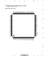
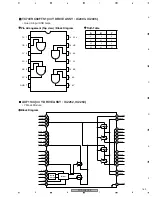
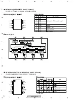
Pin Function

OC1

OC2

OUT

L

L

ALL Hi-Z

L

H

DATA

H

L

ALL L

H

H

ALL H

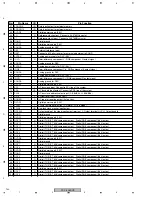
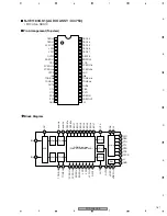
No.

Pin Name

I/O

Pin Function

1 - 30

OUT3 - OUT32

O

High-voltage push-pull output

31

N.C.

Not connected

32 - 33

V

DDH

High-voltage circuit supply

34

N.C.

Not connected

35 -  37

GND1

Ground

38

N.C.

Not connected

39

GND2

Ground

40 - 41

GND1

Ground

42

N.C.

Not connected

43 - 44

V

DDH

High-voltage circuit supply

45

N.C.

Not connected

46 - 77

OUT33 - OUT64

O

High-voltage push-pull output

78

N.C.

Not connected

79 - 80

V

DDH

High-voltage circuit supply

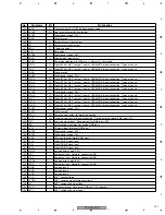
81

N.C.

Not connected

82 - 83

GND1

Ground

84

DIR

I

Setup of shift register shift direction
L = Shift into reverse (SO 

 SI)   H = Shift forward (SI 

 SO)

85

SO

I/O

Serial data input / output

86

CLK

I

Serial clock input   Fetch SI or SO data to shift register by CLK rise edge

87

LAT

I

LAT data input
L = Transfer shift register data to output latch   H = Hold data to output latch

88

V

DD

Logic supply

89

OC1

I

Output control
Control output according to the right 
truth value table

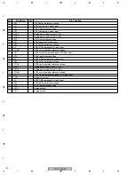
90

OC2

I

91

SI

I/O

Serial data input / output

92

CLR

I

All output reset   CLR pin : L 

 Normal operation   CLR pin : H 

 All output High

93 - 94

GND1

Ground

95

N.C.

Not connected

96 - 97

V

DDH

High-voltage circuit supply

98

N.C.

Not connected

99 - 100

OUT1 - OUT2

O

High-voltage push-pull output

Summary of Contents for PDP-436RXE

Page 1: ...ICS ASIACENTRE PTE LTD 253 Alexandra Road 04 01 Singapore 159936 PIONEER CORPORATION 2006 PDP 436SXE ARP3333 PLASMA DISPLAY SYSTEM PDP 436SXE PDP 436RXE THIS MANUAL IS APPLICABLE TO THE FOLLOWING MODEL S AND TYPE S Model Type Power Requirement Remarks PDP 436SXE WYVIXK5 AC220 240V PDP 436RXE WYVIXK5 AC220 240V PDP 436RXE WYVI5 AC220 240V For details refer to Important Check Points for good servici...

Page 2: ...be put back in place such as barriers nonmetallic knobs adjustment and compartment covershields isolation resistor capacitor etc 3 When service is required observe the original lead dress Extra precaution should be taken to assure correct lead dress in the high voltage circuitry area 4 Always use the manufacture s replacement components Especially critical components as indicated on the circuit di...

Page 3: ...c Any current measured must not exceed 0 5mA ANY MEASUREMENTS NOT WITHIN THE LIMITS OUTLINED ABOVE ARE INDICATIVE OF A POTENTIAL SHOCK HAZARD AND MUST BE CORRECTED BEFORE RETURNING THE SET TO THE CUSTOMER PRODUCT SAFETY NOTICE Many electrical and mechanical parts in PIONEER set have special safety related characteristics These are often not evident from visual inspection nor the protection afforde...

Page 4: ...and Converter Transformer In the POWER SUPPLY Unit 6 Other primary side of the POWER SUPPLY Unit High Voltage Generating Point The places where voltage is 100V or more except for the charged places described above If the places are touched there is a risk of electric shock If the procedures described in 7 1 4 POWER ON OFF FUNCTION FOR THE LARGE SIGNAL SYSTEM are performed before the power is turne...

Page 5: ... the product Please check that neither solder debris nor screws remain inside the product 8 There should be no semi broken wires scratches melting etc on the coating of the power cord Damaged power cords may lead to fire accidents so please be sure that there are no damages If you find a damaged power cord please exchange it with a suitable one 9 There should be no spark traces or similar marks on...

Page 6: ... 11 VOLTAGES 37 3 12 WAVEFORMS 42 5 PCB PARTS LIST 46 6 ADJUSTMENT 61 6 1 ADJUSTMENT REQUIRED WHEN THE SET IS REPAIRED OR REPLACED 61 6 2 USING RS 232C COMMANDS 62 6 3 SERVICE FACTORY MODE 63 6 4 LIST OF RS 232C COMMANDS 84 6 5 OUTLINE OF COMMANDS 89 6 6 METHOD FOR REPLACING THE SERVICE PANEL ASSY 100 7 GENERAL INFORMATION 104 7 1 DIAGNOSIS 104 7 1 1 PCB LOCATION 104 7 1 2 DIAGNOSIS OF SHUTDOWN PO...

Page 7: ...6SXE PDP 436RXE Number of Pixels 1024 x 768 pixels Audio Amplifier 13 W 13 W 1 kHz 10 8 Ω Speakers Bass reflex type two way system Surround System SRS FOCUS TruBass Power Requirement 220 240 V AC 50 60 Hz 291 W SXE 287 W RXE 0 8 W Standby SXE 0 4 W Standby RXE Dimensions 1076 W X 696 H X 116 D mm Weight 31 8 kg 70 1 lbs SXE 31 2 kg 68 8 lbs RXE Colour System Analogue PAL SECAM NTSC 3 58 NTSC 4 43 ...

Page 8: ...cord that is appropriate in your country or region is supplied Warranty card Cleaning cloth Ferrite core Cable tie for Ferrite core AA size battery x 2 Remote control unit Two operating instructions Remote control unit Accessories SXE AXD1515 RXE AXD1516 AED1285 ATX1039 ADG1214 ADG1223 For UK and Eire ...

Page 9: ...PDP 436SXE 9 5 6 7 8 5 6 7 8 C D F A B E ...

Page 10: ...t parts indicates the importance of the safety factor of the part Therefore when replacing be sure to use parts of identical designation Screws adjacent to mark on product are used for disassembly For the applying amount of lubricants or glue follow the instructions in this manual In the case of no amount instructions apply as you think it appropriate NOTES 19 18 23 10 21 22 20 24 2 1 4 14 3 6 8 9...

Page 11: ...able 2 23 Upper Carton See Contrast table 2 24 Mirror Mat See Contrast table 2 25 WEEE Label AAX3271 Mark No Description Part No Mark No Symbol and Description PDP 436SXE WYVIXK5 PDP 436RXE WYVIXK5 PDP 436RXE WYVI5 1 Remote Control Unit AXD1515 AXD1516 AXD1516 8 Operating Instructions Italian Spanish Dutch ARC1553 ARC1552 ARC1551 9 Operating Instructions English French German ARE1407 ARE1406 ARE14...

Page 12: ... 40 45 48 45 55 56 55 55 27 61 31 31 31 25 29 34 34 62 31 31 48 30 47 49 46 46 50 46 46 55 55 26 55 56 60 31 31 31 31 46 46 41 25 28 31 34 34 32 24 63 57 57 36 35 35 35 36 36 37 63 22 23 53 46 46 46 46 46 46 46 46 21 2 58 63 57 36 35 63 24 37 41 14 1 50 50 50 46 43 46 47 12 13 8 4 5 17 19 49 49 49 16 46 59 59 50 18 20 42 9 9 9 9 10 11 46 33 67 66 45 7 for PDP 436SXE 7 for PDP 436RXE 64 45 64 ...

Page 13: ...1 Cushion NSP 32 Speaker Stay L NSP 33 Speaker Stay R NSP 34 Wire Saddle NSP 35 Insulation Bush NSP 36 Insulation Spacer NSP 37 Spacer 38 Screw ABA1341 39 Screw 3 x 40P ABA1332 40 Hex Head Screw ABA1345 41 Screw ABA1338 42 Screw ABA1340 43 Hexagon Screw BBA1051 44 Screw AMZ30P060FTB 45 Screw TBZ40P080FTB 46 Screw AMZ30P060FTB 47 Screw ABZ30P080FTB 48 Screw BBZ40P180FTB 49 Screw APZ30P100FTB 50 Scr...

Page 14: ...PDP 436SXE 14 1 2 3 4 1 2 3 4 C D F A B E 2 3 FRONT SECTION Refer to 2 4 CHASSIS SECTION 1 2 1 5 9 6 9 7 3 11 10 12 13 15 17 14 16 16 19 18 4 2 15 ...

Page 15: ...9 Door Cushion AED1268 10 Catcher AEC2040 11 Pioneer Badge AAM1096 12 Gear Damper AXA1020 13 Screw APZ30P100FTB NSP 14 LED Lens AAK2848 15 Panel Cushin V 43 AED1256 16 Panel Cushin H 43 AED1286 17 Blind Cushion 436SX AEB1420 18 Power Button AAD4133 19 Coil Spring ABH1120 Mark No Symbol and Description PDP 436SXE WYVIXK5 PDP 436RXE WYVIXK5 PDP 436RXE WYVI5 1 Front Case Assy 43SXE AMB2892 Not used N...

Page 16: ... 2 5 CHASSIS SECTION 2 2 Note Do styling so that there is not loose of a jumper wire Refer to 2 6 AV BLOCK 18 18 9 9 9 9 7 8 20 20 19 19 19 32 33 PDP 436SXE only 26 10 11 29 30 31 21 1 17 14 12 22 10 23 21 24 2 3 23 23 10 26 19 23 6 5 13 22 22 34 23 25 16 27 25 22 16 28 23 34 23 23 13 12 15 22 5 5 5 4 28 PDP 436RXE only PDP 436RXE only ...

Page 17: ...ssis VL 436SX AMA1018 15 Front Chassis VR 436SX AMA1019 16 Panel Holder H 43 ANG2772 17 3P Housing Wire J124 ADX3204 18 Screw ABA1341 19 Screw TBZ40P080FTB 20 Screw AMZ30P060FTB 21 Screw APZ30P080FTB 22 Screw ABZ30P080FTC 23 Screw VBB30P080FNI 24 Screw BPZ30P080FTB 25 Screw BBZ30P060FTC 26 Screw APZ30P100FTB 27 Waterproof Cushion AEB1424 28 Binder See Contrast table 2 29 Insulation Sheet AED1289 3...

Page 18: ...er Switch OBE MAIN CN4011 AUDIO CN3751 OBE MAIN CN4006 R06 D TUNER CN6000 OBE MAIN CN4025 P R O O R 9 31 13 37 9 5 18 9 9 12 31 31 31 11 10 32 32 31 19 41 24 41 8 32 40 40 1 41 17 41 32 32 32 32 33 41 40 40 27 32 36 7 30 30 28 29 32 2 40 40 3 41 23 36 36 42 36 36 20 32 4 41 41 41 16 38 32 33 36 21 22 26 25 34 39 6 31 15 14 40 40 PDP 436SXE only ...

Page 19: ...4P Housing Wire J108 ADX3131 17 6P Housing Wire J121 ADX3201 18 8P Housing Wire J128 ADX3208 19 3P Housing Wire J123 ADX3203 20 3P Housing Wire J113 ADX3136 21 14P Housing Wire J122 ADX3202 22 3P Housing Wire J125 ADX3205 23 9P Housing Wire J101 ADX3124 24 Housing Wire J120 ADX3290 25 10P Housing Wire J133 ADX3214 26 6P Housing Wire J107 ADX3130 27 Conductive Plate XA ANG2776 28 Ferrite Core Holde...

Page 20: ...001 SUB POWER CN7503 OB DIGITAL CN3002 SR CN7601 IR CN8401 OB DIGITAL CN3001 Fan Motor POWER SUPPLY P5 SPEAKER BOX Assy L R 1 35 2 8 31 31 25 27 26 26 27 27 27 27 31 32 14 17 32 32 34 19 9 24 28 PDP 436RXE only PDP 436SXE only PDP 436SXE only 10 7 6 3 11 12 18 4 13 22 22 16 15 32 32 33 23 31 31 20 21 5 PDP 436RXE only 34 ...

Page 21: ...ble 2 20 Gasket A ANK1811 21 Gasket B ANK1812 22 Gasket C ANK1813 23 Gasket XE ANK1818 24 Clamp AEC1884 25 Card Spacer AEC1957 26 Locking Card Spacer AEC1801 27 Locking Card Spacer AEC2019 28 Terminal Support See Contrast table 2 29 30 31 Screw PMB30P080FNI 32 Screw AMZ30P060FTB 33 Screw See Contrast table 2 34 Screw See Contrast table 2 35 Screw See Contrast table 2 Mark No Description Part No Ma...

Page 22: ...SSY 436P AWU1135 25 29 32 32 32 32 18 21 21 23 13 12 27 28 32 26 28 for transport 32 26 32 27 29 28 14 21 27 21 27 33 21 21 21 18 18 31 16 22 11 21 21 21 33 5 9 5 5 5 4 3 7 7 7 7 2 2 2 2 8 6 27 27 10 1 17 6 6 6 19 18 22 22 22 22 22 15 15 15 30 30 30 30 15 22 22 ...

Page 23: ...ssy AWV2204 NSP 3 43 SCAN A Assy AWW1018 NSP 4 43 SCAN B Assy AWW1019 5 PCB Spacer AEC1944 6 Conductive Plate Holder AMR3446 7 Adddress Holder Assy 436 AMR3455 8 Tube Cover AMR3445 NSP 9 Chassis Assy 436 ANA1833 10 Front Chassis VL 43 AMA1016 11 Front Chassis VR 43 AMA1017 12 Sub Frame L Assy 436 ANA1864 13 Sub Frame R Assy 436 ANA1865 14 Front Chassis H Assy 43 ANA1884 15 Address Heatsink 436 ANH...

Page 24: ...ALL CONNECTION DIAGRAM 1 2 When ordering service parts be sure to refer to EXPLODED VIEWS and PARTS LIST or PCB PARTS LIST The mark found on some component parts indicates the importance of the safety factor of the part Therefore when replacing be sure to use parts of identical designation ...

Page 25: ...PDP 436SXE 25 5 6 7 8 5 6 7 8 C D F A B E SXE Only SXE Only ...

Page 26: ...PDP 436SXE 26 1 2 3 4 1 2 3 4 C D F A B E 3 2 OVERALL CONNECTION DIAGRAM 2 2 SXE OBE MAIN ASSY S AWV2238 RXE OBE MAIN ASSY R AWV2239 ...

Page 27: ...PDP 436SXE 27 5 6 7 8 5 6 7 8 C D F A B E SXE Only SXE Only SXE Only ...

Page 28: ...XT EXDIO_TXT BLK_TXT HDMI_ RCH LCH INT_HD1 VD1 TXD_DT RXD_DT SDA_AV SCL_AV SDA_AV SCL_AV CLP_PLS1 CLP_PLS2 SDA_MA SCL_MA L R RELAY MSP_RST SDA_AIR SCL_AIR DT_MON_Y C DT_SP_L R GY_SG REM_B LED B LED R LED PICOFF LED SLEEP KEY_AD1 KEY_AD2 TEMP_AIR AM_MUTE AUDIO_OUT_L R Antenna Input KEY Input 2 Component LED IR RS232C Antenna Input Output Antenna Digital Audio R06 D TUNER ASSY IC5002 HD64F3684FP IFU...

Page 29: ...R DIN5 RST_ASIC RXD_IC3 TXD_IC3 EXA EXDIO MD_A MD_B MA A0 19 DQ0 15 CN4011 to AUDIO Assy to AUDIO Assy to OB DIGITAL Assy to OB DIGITAL Assy CN4029 BLK4 FAN_CONT FAN_CONT POW A_NG_B A_MUTE A_STBY_B PSW2 SDA_DGV SCL_DGV Digital Audio signal Synchronized signal Data signal Control signal IC5207 MBM29DL162TE70TN FLASH IC5209 PQ200WNA1ZPH FAN CONTROL IC5206 MB91305PMC MAIN UCOM IC6601 PD6523A DIGITAL ...

Page 30: ...CN6000 12P PSU Connector IC3003 128Mbit SDRAM IC4100 Audio A D IC4000 Audio DAC Video Buffer Transistor Audio LPF Ope Amp CN4000 Analogue Connector IC3000 128Mbit SDRAM IC1001 COFDM IC5002 Data Bus Buffer IC5003 IC5004 Address Bus Buffer TS3 TS2 RF in RF out TS1 TS4 IF Audio L R in SPDIF out Audio L R out Analogue Audio out TXD RXD controls Digital Video out Analogue Video out I2C_tun I2C_tun I2C_...

Page 31: ...IC3401 12V Vsus_AD PS_PWDN XSUSTN_PD XDD_CNV_PD XDRIVE_PD RELAY PD_TRG_B AC_DET TEMP1 V 8V V 8V PD_MUTE SQ_PD YPR U ADR_ PD1 V 3V_D STA3 3V V 1V_D Vofs_ADJ VYPRST_ADJ STOP _SQ SCL SDA SCAN YSUS DRF_SW SCL SDA UART A_NG MODEL MODE PSW Theater VD PSIZE DRF_B XSUS EXT_PD HD RA GA BA HD VD DCLK DE A_MUTE A_STBY_B SCAN5V_PD VDD_CNV_PD YSUSSTN_PD SCAN_PD YDRIVE_PD Pulse Width Flash Memory IC3301 V 8V V ...

Page 32: ...ADDRESS ASSY IC1555 Driver IC IC1501 PEE002A K LVDS Receiver CN1501 V ADR5 CN1502 Resonance Block IC1554 Driver IC CLK LE HBLK LBLK R G B V 3V V 8V AN P BN P CN P DN P CLKN P IC1553 Driver IC V 60V V 5V IC1552 Driver IC V ADR1 Resonance Block AD1 AD2 ...

Page 33: ...ER 43 SCAN A ASSY LOWER SA1 CN2802 CN2702 SB1 IC2801 Scan IC IC2701 Scan IC IC2702 Scan IC IC2703 Scan IC IC2704 Scan IC IC2705 Scan IC IC2706 Scan IC IC2802 Scan IC IC2803 Scan IC IC2804 Scan IC IC2805 Scan IC IC2806 Scan IC Serial Data PSUS Scan Signal VH IC5V PSUS Scan Signal VH IC5V ...

Page 34: ...SYS 43 X DRIVE ASSY SUS CLAMP 1 ASSY 16 5V 16 5V 16 5V 16 5V VF 16 5V VRN 5V 5V 5V 5V 6 5V VSUS CL1 SUS CLAMP 2 ASSY VSUS CL2 X1 Logic Block Regulator 15V DC DC Conv IC1101 DK Mod Resonance Block IC1202 Mask Mod VRN DC DC Conv Reset Block X4 X3 X2 VSUS VSUS VSUS SUS OUT PSUS Drive Signal ...

Page 35: ... 16 5V 16 5V VSUS IC5V VH IC2252 Mask Mod Vprst Reg Reset Block Offset Block VOFS DC DC Conv 5V 5V 16 5V 5V 5V 16 5V 16 5V 16 5V Scan Signal 60V IC5V IC5V 5V VOFS VOFS VSUS 16 5V SUSOUT 6 5V 5V VF VSUS IC2253 Mask Mod IC2101 DK Mod Resonance Block Logic Block Regulator Soft D Block IC5V VF DC DC Conv Photo Coupler Block VH DC DC Conv ...

Page 36: ...Y UNIT RC101 RY102 LIVE NEUTRAL PRIMARY SECONDARY STB3 3V 16 5V 12V 60V VSUS VSUS_CONT T501 PFC Q202 Q203 RELAY EXT_PD 390V D121 D123 T401 T301 T121 P3 Z501 Switching Z121 P1 P2 P7 P6 P5 P4 16 5V 7 0V Z901 PS_PD VSUS_ADJ Q403 Q402 Switching Switching Z301 Switching Switching P8 ...

Page 37: ...XD_DT GND DT_FNC GND CLK_DT GND Y7_DT Y6_DT GND Y5_DT Y4_DT GND Y3_DT Y2_DT GND Y1_DT Y0_DT GND CB7_DT CB6_DT GND GND GND GND TXD_DT RXD_DT GND DT_FNC GND CLK_DT GND Y7_DT Y6_DT GND Y5_DT Y4_DT GND Y3_DT Y2_DT GND Y1_DT Y0_DT GND CB7_DT CB6_DT GND GND GND 0 3 3 3 3 0 3 3 0 0 to 3 3 0 0 to 3 3 0 to 3 3 0 0 to 3 3 0 to 3 3 0 0 to 3 3 0 to 3 3 0 0 to 3 3 0 to 3 3 0 0 to 3 3 0 to 3 3 0 0 0 1 2 3 4 5 6...

Page 38: ...16 17 18 19 20 21 22 23 24 25 26 27 28 29 30 31 32 33 34 35 36 37 38 39 40 OBE MAIN ASSY POWER SUPPLY UNIT CN4006 KM200NA16 Voltage V CN7503 KM200NA16 No Name Name No AC_DET RELAY GND V 3_3V_STB GND V 5_1V_STB V 5_1V V 5_1V GND V 6_8V GND V 12V GND V 17V GND V 35V AC_DET RELAY GND V 3_3V_STB GND V 5_1V_STB V 5_1V V 5_1V GND V 6_8V GND V 12V GND V 17V GND V 35V 3 3 3 3 0 3 3 0 5 1 5 1 5 1 0 6 6 0 1...

Page 39: ...0 32 GND TP3025 33 GA IN9 I 0 3 3 TP3067 34 GA IN8 I 0 3 3 TP3066 35 GA IN7 I 0 3 3 TP3065 36 GA IN6 I 0 3 3 TP3064 37 GA IN5 I 0 3 3 TP3063 38 GA IN4 I 0 3 3 TP3062 39 GA IN3 I 0 3 3 TP3061 40 GA IN2 I 0 3 3 TP3060 41 GND TP3025 42 BA IN9 I 0 3 3 TP3077 43 BA IN8 I 0 3 3 TP3076 44 BA IN7 I 0 3 3 TP3075 45 BA IN6 I 0 3 3 TP3074 46 BA IN5 I 0 3 3 TP3073 47 BA IN4 I 0 3 3 TP3072 48 BA IN3 I 0 3 3 TP...

Page 40: ...ND 34 GND 35 V 3V_D O 3 3 TP3607 36 V 3V_D O 3 3 TP3607 37 GND 38 ADRS_3 O 0 39 ADRS_2 O 0 40 GND Pin No Name I O Function Voltage V TP 1 N C 2 ADR_PD I 0 4 TP3502 3 N C 4 GND 5 V 8V O 8 TP3618 6 V 8V O 8 TP3618 7 GND 8 GND 9 N C 10 TA O 1 1 4 11 TA O 1 1 4 12 N C 13 GND 14 N C 15 TB O 1 1 4 16 TB O 1 1 4 17 N C 18 GND 19 N C 20 TC O 1 1 4 21 TC O 1 1 4 22 N C 23 GND 24 N C 25 TCLK O 1 1 4 26 TCLK...

Page 41: ..._D O 1 24 TP3022 4 V 1V_D 1 24 TP3022 5 GND TP3024 6 GND TP3024 7 V 3V_D O 3 3 TP3023 8 V 3V_D O 3 3 TP3023 Pin No Name I O Function Voltage V TP 1 STA3 3V O 3 3 TP3159 2 TEMP1 I 2 TP3161 3 GND TP3162 CN3503 D17 ADDRESS ASSY CN3504 D18 ADDRESS ASSY CN5601 D1 POWER SUPPLY UNIT CN3002 D12 MAIN ASSY CN3151 D24 PANEL SENSOR ASSY Not connected Adderss PD signal Not connected GND 8V Vcc 8V Vcc GND GND N...

Page 42: ...v 3 IC4804 pin 57 A_TUNER_V V 1V div H 20µsec div 4 TP4815 Component Y GY_AD V 500mV div H 10µsec div 5 TP4816 Component Cb BCB_AD V 500mV div H 10µsec div 6 TP4817 Component Cr RCR_AD V 500mV div H 10µsec div 7 TP4818 SCART G GY_MVDEC V 500mV div H 20µsec div 8 TP4819 SCART B BCB_MVDEC V 500mV div H 20µsec div 9 TP4820 SCART R RCR_MVDEC V 500mV div H 20µsec div 10 IC4804 pin 49 MAIN_Y MAIN_Y V 50...

Page 43: ...E V 2V DIV H 2ms DIV 2 CH1 CH2 CH3 CH1 TP3030 CLK CH2 TP3033 HD CH3 BA 2 DATA V 2V DIV H 100ns DIV 5 CH1 CH2 CH3 CH1 TP3194 YPP U CH2 TP3197 ADR_PD1 CH3 TP3195 IC3155 6 V 2V DIV H 2ms DIV 3 CH1 CH2 CH3 CH1 TP3032 VD CH2 TP3033 HD CH3 TP3031 DE V 2V DIV H 10µs DIV 6 CH1 CH2 CH1 TP3032 VD CH2 TP3179 STOP_SQ V 2V DIV H 2ms DIV OB DIGITAL ASSY DIGITAL IF BLOCK MODULE UCOM BLOCK ...

Page 44: ...v CH4 IC1555 pin 14 LE V 1V div H 2msec div CH5 IC1555 pin 19 HBLK V 1V div H 2msec div CH6 IC1555 pin 17 LBLK V 1V div H 2msec div 3 3 1 3 2 3 3 3 4 3 5 3 6 Incoming signal of TCP Resonance part Input VIDEO Signal Checkered pattern of Black White MKSS13 CH1 IC1555 pin 3 VDD2 V 10V div H 200nsec div CH2 IC1555 pin 9 A3 V 1V div H 200nsec div CH3 IC1555 pin 16 CLK V 1V div H 200nsec div CH4 IC1555 ...

Page 45: ...E Assy CH2 TP2008 CLK K2002 GND D V 1V div H 2msec div X DRIVE Assy CH3 TP2003 SI H K2002 GND D V 1V div H 2msec div X DRIVE Assy CH4 TP2004 CLR K2002 GND D V 1V div H 2msec div X DRIVE Assy CH5 TP2005 OC2 K2002 GND D V 1V div H 2msec div X DRIVE Assy CH6 TP2006 OC1 K2002 GND D V 1V div H 2msec div X DRIVE Assy 5 5 1 5 2 5 3 5 1 5 2 5 3 Reset pulse signal CH1 R1277 XPSUS K1203 SUSGND V 100V div H ...

Page 46: ...AWV2237 AWV2237 AWV2237 2 AUDIO ASSY AWW1087 AWW1087 AWW1087 2 SR ASSY AWW1088 AWW1088 AWW1088 2 TUNER ASSY AWW1089 AWW1089 AWW1089 2 FRONT ASSY AWW1090 AWW1090 AWW1090 2 LED ASSY AWW1091 AWW1091 AWW1091 2 IR ASSY AWW1092 AWW1092 AWW1092 2 KEY ASSY AWW1093 AWW1093 AWW1093 2 PANEL SENSOR ASSY AWW1094 AWW1094 AWW1094 2 SUBPOWER ASSY AWW1095 AWW1095 AWW1095 1 OB DIGITAL ASSY AWV2244 AWV2244 AWV2244 N...

Page 47: ...EHVKW101M6R3 C1010 CEHVKW2R2M50 C1102 CEHVKW331M6R3 C1018 C1027 C1029 C1050 CEHVKW470M16 C1056 C1057 CEHVKW470M16 C1015 CKSRYB102K50 C1013 C1021 C1040 C1041 C1045 CKSRYB103K50 C1001 C1003 C1017 C1022 CKSRYB104K16 C1025 C1026 C1030 C1035 C1037 CKSRYB104K16 C1039 C1049 C1053 C1058 C1062 CKSRYB104K16 C1036 CKSRYB105K10 RESISTORS All Resistors RS1 16S J OTHERS FU1200 CHIP FUSE 0 25A XEK1003 X1100 CRYS...

Page 48: ...RS IC5001 CIMAXSP2L IC5000 ST890CDR IC5002 TC74LCX245FTS1 IC5003 IC5004 TC74LCX373FT Q5000 2SC4081 Q5001 DTA143EUA Q5002 DTC124EUA Mark No Description Part No CAPACITORS C5005 C5100 CEHVKW470M16 C5001 CKSRYB105K10 C5003 C5004 C5006 C5008 C5013 CKSRYF104Z16 RESISTORS R5014 R5019 R5022 R5024 R5030 RAB4CQ470J R5032 R5036 R5038 R5045 R5050 RAB4CQ470J Other Resistors RS1 16S J OTHERS CN5000 PCMCIA CONN...

Page 49: ...4244 C4269 4700 63 ACH1429 C4259 CCSRCH471J50 C4205 C4219 C4224 C4228 CEHVKW101M6R3 C4226 CEHVKW220M16 Mark No Description Part No C4213 C4234 CEHVKW470M16 C4214 CKSRYB104K16 C4203 C4217 C4223 CKSRYB105K10 C4266 CKSRYB471K50 C4229 C4252 CKSSYB104K10 C4232 CKSSYB471K50 C4204 C4212 C4227 C4251 C4256 CKSSYF104Z16 C4258 C4261 C4262 C4265 C7267 CKSSYF104Z16 C4211 C4225 10 16 DCH1165 RESISTORS R4221 R42...

Page 50: ...ACG7046 C4877 C4880 CCSRCH181J50 C4859 CCSRCH331J50 C4861 CCSRCH680J50 C4885 C4888 CCSRCH681J50 C4822 C4862 CEHVKW101M6R3 C4802 C4805 C4806 C4808 CKSRYB105K10 C4813 C4814 C4820 C4833 C4834 CKSRYB105K10 C4836 C4838 C4841 C4847 C4848 CKSRYB105K10 Mark No Description Part No C4850 C4851 C4878 C4879 CKSRYB105K10 C4899 C4905 CKSRYB105K10 C4837 CKSRYB474K10 C4853 C4858 C4860 C4865 CKSSYB103K16 C4869 C48...

Page 51: ...SYF104Z16 RESISTORS R5409 R5432 68 1 16W ACN1251 R5404 R5428 R5429 R5434 R5435 BCN1067 47 1 16W R5439 R5457 R5476 RAB4CQ103J R5460 RAB4CQ680J Mark No Description Part No Other Resistors RS1 16SS J OTHERS X5401 6 000MHz CRYSTAL ASS1193 VDEC BLOCK SEMICONDUCTORS IC6002 HY57V161610ETP 8 IC6003 UPD64015AGM UEU COILS AND FILTERS F6001 F6002 F6010 F6011 EMI FILTER CCG1162 CAPACITORS C6056 C6088 10 6 3 A...

Page 52: ...C6602 TC74LCX125FT IC6603 TC74VHC125FTS1 COILS AND FILTERS F6628 CHIP BEADS FILTER ATX1058 F6601 F6603 EMI FILTER CCG1162 CAPACITORS C6632 10 6 3 ACG7046 C6604 CCSRCH221J50 Mark No Description Part No C6631 CKSSYB102K50 C6601 C6603 C6606 C6610 CKSSYF104Z16 C6613 C6617 C6619 C6621 C6623 CKSSYF104Z16 C6625 C6627 C6629 C6630 CKSSYF104Z16 RESISTORS R6603 R6605 68 1 16W ACN1251 R6611 R6614 R6618 R6653 ...

Page 53: ...5 SCREW VBB30P100FNI KN3751 KN3752 WRAPPING TERMINAL VNF1084 SR ASSY SEMICONDUCTORS IC7601 MAX3232CPW Q7608 HN1B04FU Mark No Description Part No TH7601 TH05 3H103F CAPACITORS C7608 CEHVKW100M16 C7601 CKSRYB103K50 C7603 C7607 C7614 CKSSYF104Z16 RESISTORS R7626 RS1 16S4701F R7602 R7605 RS1 16SS J Other Resistors RS1 16S J OTHERS CN7602 9P D SUB SOCKET AKP1213 7602 SCREW TERMINAL VNE1949 TUNER ASSY S...

Page 54: ...8402 CKSRYB103K50 C8403 CKSSYB102K50 C8404 CKSSYF104Z16 RESISTORS R8401 R8403 R8404 RS1 16SS J Other Resistors RS1 16S J Mark No Description Part No OTHERS CN8401 L PLUG 3P KM200NA3L KEY ASSY SWITCHES AND RELAYS S8451 S8456 VSG1024 CAPACITORS C8451 C8453 CCSRCH101J50 RESISTORS Other Resistors RS1 16S J PANEL SENSOR ASSY SEMICONDUCTORS Q8602 HN1B04FU TH8601 TH05 3H103F CAPACITORS C8606 C8607 CKSRYB...

Page 55: ...M29PL160TD75TN IC3304 PST3610UR IC3302 IC3305 PST3628UR IC3303 SN74AHC08PW Q3302 HN1C01FU Q3301 RN1901 Mark No Description Part No CAPACITORS C3311 CCSRCH470J50 C3317 CCSRCH471J50 C3315 CKSRYB104K16 C3304 C3307 C3309 CKSRYB472K50 C3305 C3310 CKSSYB102K50 C3301 C3303 C3306 C3308 C3316 CKSSYF104Z16 RESISTORS Other Resistors RS1 16SS J OTHERS X3302 102 5 MHz CRYSTAL ASS1188 ASTRA BLOCK SEMICONDUCTORS...

Page 56: ...PACITORS C2701 C2711 C2721 0 1U 250V ACG1088 C2731 C2741 C2751 0 1U 250V ACG1088 C2710 C2720 C2730 C2740 C2750 CCSRCH181J50 C2760 CCSRCH181J50 C2708 C2709 C2718 C2719 CCSRCH331J50 C2728 C2729 C2738 C2739 CCSRCH331J50 C2748 C2749 C2758 C2759 CCSRCH331J50 C2705 C2707 C2715 C2717 CCSRCH390J50 C2725 C2727 C2735 C2737 CCSRCH390J50 C2745 C2747 C2755 C2757 CCSRCH390J50 C2703 C2713 C2723 C2733 C2743 CKSRY...

Page 57: ...25 Z D1281 1SS302 D1201 1SS355 D1252 CRH01 Mark No Description Part No D1282 UDZS16 B D1251 UDZS5R6 B COILS AND FILTERS L1204 L1211 INDUCTOR ATH1186 F1201 INDUCTOR CTF1449 L1201 L1205 L1231 LFEA100J CAPACITORS C1214 C1217 ACE1178 C1297 C1298 3300P 630V ACG1129 C1212 C1213 ACH1424 C1231 CEHAT101M10 C1206 CEHAT101M25 C1283 CEHAT2R2M2E C1208 CEHAT470M16 C1222 C1272 CEHAT470M25 C1221 CKSRYB105K6R3 C12...

Page 58: ... IC2101 AXF1145 IC2141 BA10393F Mark No Description Part No Q2141 2SC4081 D2101 D2105 D1FL40 COILS AND FILTERS L2101 L2102 CHOKE COIL ATH1155 L2103 L2106 CHOKE COIL ATH1193 CAPACITORS C2131 C2134 C2136 ACE1178 C2103 C2107 C2108 0 22UF 250V ACG1112 C2104 C2106 470P 630V ACG1126 C2109 C2112 3300P 630V ACG1129 C2101 C2145 CKSRYB105K6R3 C2141 C2143 C2144 CKSSYB104K10 C2102 CKSYB105K25 RESISTORS R2101 ...

Page 59: ...1 16S J OTHERS CN2401 CN2402 AKM1200 15P BRIDGE CONNECTOR AKM1200 Y VH D D CON BLOCK SEMICONDUCTORS IC2531 BA10358F IC2502 MIP2E3DMC IC2503 PS2701A 1 L IC2534 IC2535 TA76431FR Q2533 2SC2412K Mark No Description Part No Q2531 2SC3425 Q2532 2SD2568 Q2511 HN1C01FU D2534 1SS355 D2522 D2524 CRH01 D2523 D2532 D1FK60 D2533 UDZS33 B D2536 UDZS4R7 B D2530 D2531 UDZS8R2 B COILS AND FILTERS T2503 CONVERTER T...

Page 60: ...103K50 C2601 C2604 C2609 CKSRYB104K16 C2602 C2615 CKSRYB105K6R3 C2603 CKSRYF104Z50 C2611 CKSSYB104K10 RESISTORS R2613 RAB4C472J R2641 R2642 RS1 10S224J R2629 RS1 16S1002F R2625 R2626 RS1 16S1501F R2608 R2612 R2630 R2632 R2635 RS1 16S4701F R2618 RS1 16S4702F R2636 RS1 16S5601F R2652 RS1 16S6801F R2627 RS3LMF151J VR2601 CCP1390 Other Resistors RS1 16S J POWER SUPPLY UNIT POWER SUPPLY Unit has no ser...

Page 61: ... the 7 1 5 BACKUP WHEN THE PANEL UNIT IS ADJUSTED OBE MAIN Assy Replacement of components IC4804 IC4806 IC5202 IC5207 IC6003 and IC6201 on the circuitboard can cause malfunction and or failure If replacement is necessary the assembly must be replaced 43 X DRIVE Assy No adjustment required No adjustment required OBE MAIN assy No adjustment required R06 D TUNER Assy No adjustment required Other asse...

Page 62: ...en within 3 seconds after the key is released use the SET key on the remote control unit to set to RS 232C The path is switched to that for RS 232C control The baud rate becomes 9 600 bps To Switch RS 232C control to ON Hold the VOLUME or key on the remote control unit pressed for 3 10 seconds during Standby mode Then within 3 seconds after the key is released hold the 2 screen key on the remote c...

Page 63: ...vice Factory mode is entered including when the FAY command is received FREEZE Mask Control ORBITER Operating at center value User data User data will be treated as follows User data on picture and audio quality adjustments are not reflected and factory preset data are output user data will be retained in memory When the unit enters Factory mode the current audio quality adjustment data will still...

Page 64: ...e 1 FAN 2 DTB ANT VOLT PDP 436SXE Only Up Down 5 OPTION mode 1 PEAK LIMITER 2 EDID WRITE MODE 3 CH PRESET 4 PANEL FACTORY mode 1 PANEL INFORMATION 2 PANEL WORKS 3 POWER DOWN 4 SHUT DOWN 5 PANEL 1 ADJ 6 PANEL 2 ADJ 7 PANEL REVICE 8 ETC 9 MASK SETUP 6 INITIALIZE mode 1 SYNC DET 2 SG MODE 3 SG PATTERN 4 SIDE MASK LEVEL 5 FINAL SETUP 6 SR 7 UART SELECT 8 HDMI INTR POSITION MUTE MUTE MUTE 3 COMMON ADJ ...

Page 65: ... 27 28 29 30 31 32 33 34 35 36 37 38 39 40 2 3 I N F ORMA T I ON V 1 1 6 V D 1 0 1 N T V J H S 6 1 2 3 4 Four parameters are displayed Note See SIG Mode Tables See next page 1 Input function 2 SIG mode and screen size 3 Color system and signal type Input Functions On Screen Display INPUT 1 4 AV 1 4 Analogue Tuner AIR Digital Tuner ARD 4 Option Destination etc Options On Screen Display Advanced PDP...

Page 66: ...IG Mode table for video signals resolutions and V frequencies Selection of the screen size by the user is displayed 1st and 2nd 3rd and 4th Signal Type Fv Hz Fh kHz 10 50 SDTV 625i 50 000 15 625 60 SDTV 525i 60 000 15 750 12 60 SDTV 525i PAL60 60 000 15 750 20 50 SDTV 625p 50 000 31 250 60 SDTV 525p 60 000 31 500 30 50 HDTV 1125i 50 000 28 125 60 HDTV 1125i 60 000 33 750 40 50 HDTV 750p 50 000 37 ...

Page 67: ...lity data forCARRERA MANTA PIC DAT Module microcomputer for the PDP MODULE Program for ASTRA MANTA for the PDP SEQ PRG Sequence data for ASTRA MANTA Video SQ DT V Sequence data for ASTRA MANTA PC SQ DT P Device On Screen Display Version Display Remarks DTB Software Version DTB 4 character PDP 436SXE only Teletext ucom Software Version TEXT 60 character 20 character x 3 User Password PASSWORD 4 cha...

Page 68: ...computer communication MA SRL Abnormality in 3 wire Serial Communication of the Main microcomputer IF Communication failure of IF microcomputer MULTI1 MANTA communication failure MULIT1 I P MANTA communication failure I P D SEL MANTA communication failure D SEL MA IIC Abnormality in Main microcomputer IIC communication FE1 Analog Tuner 1 Front End 1 MPX MPX AV SW AV Switch RGB SW RGB Switch M VDEC...

Page 69: ...0 C SD process stats FAN The value of the Fan rotating state is displayed STOP stopped MIN slow speed MAX high speed 1 1 2 3 4 5 6 7 8 9 10 11 12 13 14 15 16 17 18 19 20 21 22 23 24 25 26 27 28 29 30 31 32 33 34 35 36 37 38 39 40 2 3 4 5 6 7 8 9 10 11 12 13 14 15 16 I T EMP E E R A T U R N F ORMA T I ON E T MP 2 1 3 0 M I N F A N 1 1 V D 1 6 0 1 N T V J H S 6 This displays the internal set tempera...

Page 70: ...V D 1 6 0 1 N T V J H S 6 Technical examination display Reading status registers in HDMI receiver and displaying them by HEX value HDMI SIGNAL INFO 1 SA Context 0x60 4E Video DE pixels 7 0 4F Video DE pixels 11 8 50 Video DE lines 7 0 51 Video DE lines 10 8 55 Video status interlace or progressive sync polarity 0x68 2A Audio in channel status PCM copy information etc 30 Audio in SPDIF channel stat...

Page 71: ...hod 7 0 07 N Value for audio clock regeneration method 15 8 08 N Value for audio clock regeneration method 19 16 0C CTS Value for audio clock regeneration method 7 0 0D CTS Value for audio clock regeneration method 15 8 0E CTS Value for audio clock regeneration method 19 16 Tuner signal information in MVDEC SVDEC Device SA Context MVDEC 00h Signal distinction 1 01h Signal distinction 2 02h Flag de...

Page 72: ... INFORMATION 2 PANEL WORKS 3 POWER DOWN 4 SHUT DOWN 5 PANEL 1 ADJ 6 PANEL 2 ADJ 7 PANEL REVICE 8 ETC 9 MASK SETUP Summary Descuiption Display DIGITAL Assy software version and backup state etc Display pulse meter and hour meter etc Display power down history Display shut down history Module u com detecting Adjust sustain wave form and drive power Adjust panel white balance and ABL Set the correcti...

Page 73: ...valent to PRL 6 5 G LOW 000 to 999 Equivalent to PGL 6 6 B LOW 000 to 999 Equivalent to PBL 6 7 ABL 000 to 255 Equivalent to ABL 7 PANEL REVISE 7 1 R LEVEL LV 0 to LV 7 Equivalent to RRL 7 2 G LEVEL LV 0 to LV 7 Equivalent to RGL 7 3 B LEVEL LV 0 to LV 7 Equivalent to RBL 8 ETC 8 1 BACKUP DATA NO OPRT TRANSFER or ERR Equivalent to BCP 8 2 DIGITAL EEPROM NO OPRT DELETE REPAIR Equivalent to FAJ UAJ ...

Page 74: ...g to PANEL WORKS UP Shifting to MASK SETUP SEL MASK ON OFF L R Updating displayed information A P N E L A P N E L N I F O R A M O M D U L E 0 1 M S 0 S 1 E S Q P G R 0 1 M A Q S D T V 5 2 0 W Q S D T P 5 2 0 W I D G E P E A D J S U T D E A B C K U P N O A D T A E S R I A L _ _ _ _ _ _ _ _ _ _ _ _ _ _ _ 0 A 2 T I O N I N 1 5 2 0 6 0 R G B H E S 6 F A C T 1 5 10 15 16 1 5 10 15 20 25 30 32 2 PANEL W...

Page 75: ... inability UNKNOW 4 SHUT DOWN Basically data acquired with the command QSD for MDU IIC subcategory data are also displayed are displayed with the values from the hour meter when the shutdown occurred Causes of shutdown and corresponding OSD indications A P N E L H S U T O D W A M I N U S B N 1 4 2 0 0 0 1 2 A U D O I T E M 1 P O M 3 M D I I C E E P R 4 5 7 S Q C I V O L I C 8 6 M D I I C H 2 3 M 1...

Page 76: ... MASK ON OFF A P N E L L 1 B T 6 0 V S I N 1 5 2 0 6 0 R G B H E S 6 F A C T X S U S B A J P N E L 1 A D 2 1 8 1 5 10 15 16 1 5 10 15 20 25 30 32 Type of WB ABL Tables Type of Drive Sequences Standard Video MASK ON Nonstandard Video PC TBL1 48VS 60PS Not used for consumer products TBL2 50VS 50VN 70PS TBL3 60VS 60VN TBL4 72VS Only Mask indication 75VS 75VN No Items Adjustment Setting Value Remarks ...

Page 77: ...3 B HIGH 000 to 511 Equivalent to PBH 4 R LOW 000 to 999 Equivalent to PRL 5 G LOW 000 to 999 Equivalent to PGL 6 B LOW 000 to 999 Equivalent to PBL 7 ABL 000 to 255 Equivalent to ABL DOWN Shifting to the next item UP Shifting to the previous item RIGHT Adding by one to the adjustment value LEFT Subtracting by one from the adjustment value VOL Adding by 10 to the adjustment value VOL Subtracting b...

Page 78: ...arks 1 R LEVEL LV 0 to LV 7 Equivalent to RRL 2 G LEVEL LV 0 to LV 7 Equivalent to RGL 3 B LEVEL LV 0 to LV 7 Equivalent to RBL DOWN Shifting to ETC UP Shifting to PANEL 2 ADJ SEL MASK ON OFF SET Shifting to the next nested layer 7 Key operation DOWN Shifting to the next item UP Shifting to the previous item RIGHT Adding by one to the adjustment value LEFT Subtracting by one from the adjustment va...

Page 79: ...ayer 7 Key operation DOWN Shifting to the next item UP Shifting to the previous item RIGHT Adding by one to the adjustment value LEFT Subtracting by one from the adjustment value SET Determining the setting value and shifting to the upper layer SEL MASK ON OFF 7 Key operation No Items Adjustment Setting Value Remarks 1 BACKUP DATA NO OPRT TRANSFER ERR is indicated when no data are in the backup EE...

Page 80: ... to MKS S00 2 SGL MASK 01 48V 50V 60V 60P 70P 72V 75V Equivalent to MKS S01 3 SGL MASK 02 Equivalent to MKS S02 4 5 CMB MASK 08 Equivalent to MKC S08 6 CMB MASK 09 Equivalent to MKC S09 DOWN Shifting to PANEL INFORMATION UP Shifting to ETC SEL MASK ON OFF SET Shifting to the next nested layer 7 Key operation DOWN Shifting to the next MASK UP Shifting to the previous MASK RIGHT Changing MASK sequen...

Page 81: ...ct boud Rate on RS 232C Communication 8 HDMI INTR POSITION Only for the technical use 1 1 2 3 4 5 6 7 8 9 10 11 12 13 14 15 16 17 18 19 20 21 22 23 24 25 26 27 28 29 30 31 32 33 34 35 36 37 38 39 40 2 3 4 5 6 7 8 9 10 11 12 13 14 15 16 I N I T I S G M A A N MV D E C Y OD E E A L I Z 1 1 V D 1 6 0 1 N T V J H S 6 2 SG MODE The route of the Test Signal from the MVDEC is chosen by this function After...

Page 82: ...ching should be done correctly in the factory mode Y or G signal from SG should be input to the AVI terminal of the MVDEC when the SG signal is output The function of the blanking offset 50 IRE should be OFF during the SG mode The setting of the Y C separation function should be set to the NTSC during the SG mode Only the RGB and Component signals can be output during SG mode so only the Y signal ...

Page 83: ... this menu is YES final setup will be done 1 1 2 3 4 5 6 7 8 9 10 11 12 13 14 15 16 17 18 19 20 21 22 23 24 25 26 27 28 29 30 31 32 33 34 35 36 37 38 39 40 2 3 4 5 6 7 8 9 10 11 12 13 14 15 16 I N I T I S R ON E A L I Z 1 1 V D 1 6 0 1 N T V J H S 6 1 1 2 3 4 5 6 7 8 9 10 11 12 13 14 15 16 17 18 19 20 21 22 23 24 25 26 27 28 29 30 31 32 33 34 35 36 37 38 39 40 2 3 4 5 6 7 8 9 10 11 12 13 14 15 16 ...

Page 84: ... Factory mode on FST Final Set Up G GSL Adjusting side mask G I INA Selection of tuner for terrestrial analog signals INC Selection of tuner for terrestrial digital signals INPS01 Input selection input 1 INPS02 Input selection input 2 INPS03 Input selection input 3 INPS04 Input selection input 4 O OSDS00 Turning the On Screen Display off Permit On Screen Display OSDS01 Turning the On Screen Displa...

Page 85: ...Used only when the panel is replaced D DRV S00 DRIVE OFF Sequence drive off S01 DRIVE ON Sequence drive on E ESV S00 POWER CONTROL NORMAL Setting Power Consumption mode to 4 split normal curve S01 POWER CONTROL MODE1 Setting Power Consumption mode to 2 split normal curve S02 POWER CONTROL MODE2 Setting Power Consumption mode to 2 split power saving curve F FAJ FINISH ADJUSTMENT Determining the fla...

Page 86: ...ck raster S25 MASK SINGLE 25 Window Hi 870Lo 102 PATTAN3 S26 MASK SINGLE 26 Window Hi 1023Lo 102 PATTAN3 S27 MASK SINGLE 27 Window Hi 1023 Pattern 3 S28 MASK SINGLE 28 Window Hi 1023 4 Pattern 3 S29 MASK SINGLE 29 Window Hi 1023 1 25 Pattern 3 S30 MASK SINGLE 30 Window 1 7LINE Pattern 3 S51 MASK SINGLE 51 Raster White S52 MASK SINGLE 52 Raster Red S53 MASK SINGLE 53 Raster Green S54 MASK SINGLE 54...

Page 87: ...g various input signal data QPD QUEST POWER DOWN Acquiring logs of power down points QPM QUEST PULSE METER Acquiring data of the pulse meter QPW QUEST PANEL WHITE BALANCE Acquiring panel white balance adjustment values QS1 QUEST STATUS 1 Acquiring data on the unit such as the version of the program QS2 QUEST STATUS 2 Acquiring data on the status of the unit such as temperature QSD QUEST SHUT DOWN ...

Page 88: ...equency in Mask mode to VD 60 Hz S05 FREQENCY THEATER 72Hz Setting the frequency in Mask mode to VD 72 Hz S06 FREQENCY 75Hz Setting the frequency in Mask mode to VD 75 Hz S13 FREQENCY PC 60Hz Setting the frequency in Mask mode to PC 60 Hz S14 FREQENCY PC 70Hz Setting the frequency in Mask mode to PC 70 Hz S22 FREQENCY VIDEO 50Hz NONSTD Setting the frequency in Mask mode to VD 50 Hz nonstandard S23...

Page 89: ... 12 Sequence Version 50VIDEO 4 byte 13 Sequence Version 50PC 4 byte 14 MAIN comma 1 byte 15 Product Infomation 1 1 byte 16 Product Infomation 2 1 byte 17 Product Infomation 3 1 byte 18 Product Infomation 4 1 byte 19 Version of IF microcomputer 4 byte 20 Version of Main microcomputer 8 byte 21 Boot Version of Main microcomputer 4 byte 22 Program Version of CARRERA MANTA 8 byte 23 Boot Data Version ...

Page 90: ... byte 29 8th latest NG data 1 byte 30 Data of subcategory for the 8th latest NG 1 byte 31 Data of hour meter for the 8th latest NG 7 byte 32 Data of temperature for the 8th latest NG 3 byte Data Cause of Shutdown Remarks 0 Normal 1 Failure of communication to Module microcomputer 2 3 wire Serial Communication of Main microcomputer Subcategory 1 3 IIC Communication failure of Main microcomputer Sub...

Page 91: ...munication of Main microcomputer subcategory 3 Data Cause of Shutdown Data Cause of Shutdown 0 Non subcategory A AD PLL 1 Analog Tuner 1 Front End 1 B HDMI 2 C TMDS Tx 3 MPX D TMDS Rx 4 AV Switch E M2 Communication 5 RGB Switch F M2 Busy 6 CCD G 64k EEPROM 7 GCR 8 Main VDEC 9 Data Cause of Shutdown Remarks 0 Non subcategory 1 Failure to DTB Starting 2 Communication failure to DTB ...

Page 92: ... No data PD data 0 No PD data 1 Not used 2 POWER 3 SCAN 4 SCN 5V 5 Not used 6 Y DCDC 7 Y SUS 8 ADRS 9 X DRV A X DCDC B X SUS C Not used D SQ IC E Not used F Specification inability SD main data 0 No SD 1 SQ IC 2 MDU IIC 3 RST2 4 Panel having high temperature 5 Short circuited speaker Operation status induced by SD 0 Normal 1 Relay off completed 2 During warning indication MASK indication 0 MASK OF...

Page 93: ...value 1Byte 0 11 B RIVISE setting value 1Byte 0 CS 2Byte B7 Command Format Effective Operation Modes Function Remarks QIP All operations To acquire data on operations of the panel Return data 3 ECO 39 DATA 2 CS 44Byte 7 Acquisition of other data on the panel QIP The command QIP is for acquiring data other than those available with QS1 data necessary before turning the power on and QS2 data to info...

Page 94: ...ting n 0 to F Transition of brightness by protective operations 0 Upper limit state for brightness 1 Brightness being reduced 2 Lower limit state for brightness 3 Brightness being increased The output data on the accumulated number of pulses for each block are calculated in the following way the high order 4 bytes of the accumulated number of pulses for each block are converted into a decimal numb...

Page 95: ...r meter for the fifth latest PD 8byte 00000715 16 Sixth latest 1st PD data 1byte A 17 Sixth latest 2nd PD data 1byte 2 18 Data from the hour meter for the sixth latest PD 8byte 00000552 19 Seventh latest 1st PD data 1byte A 20 Seventh latest 2nd PD data 1byte 0 21 Data from the hour meter for the seventh latest PD 8byte 00000213 22 Eighth latest 1st PD data 1byte D 23 Eighth latest 2nd PD data 1by...

Page 96: ...e hour meter for the fifth latest SD 8byte 00000852 16 Sixth latest SD data 1byte 2 17 Sixth latest SD subcategory data 1byte 5 18 Data from the hour meter for the sixth latest SD 8byte 000000451 19 Seventh latest SD data 1byte 0 20 Seventh latest SD subcategory data 1byte 0 21 Data from the hour meter for the seventh latest SD 8byte 00000000 22 Eighth latest SD data 1byte 0 23 Eighth latest SD su...

Page 97: ...otection 1byte 1 21 Result of detection for external protection 1byte 1 22 Transition of protection operation 1byte 0 23 Reservation 4byte CS 2Byte 27 If data for an item cannot be obtained during Standby mode the return data for that item will be The types of data for Items 1 3 in the table drive sequence standard nonstandard and type of ABL WB tables are the same as with the command QPW Each tot...

Page 98: ...ing while Mask is ON Setting while Mask is OFF Remarks Detection of still picture OFF ON Detection of cracking in the panel OFF ON Scanning protection OFF ON 7 Setting for Factory mode permission prohibition FAY FAN PFY PFN The commands FAY FAN and PFY PFN are for prohibiting permitting panel adjustment commands during normal operation and are to be used to avoid accidental change of panel adjustm...

Page 99: ...al EEPROM are copied to the same addresses of the backup EEPROM Copying will be executed immediately before the relay of normal operation is off When the command BCP is received while a warning indicating that backup copying has not been completed is displayed conditions Digital EEPROM not adjusted and backup EEPROM adjusted backed up data will be copied to the Digital EEPROM and various adjustmen...

Page 100: ...rt Enter VOF112 Reference adjustment of the Vyprst voltage Ex 50 inch Vyprst 270 V Check the conversion chart Enter VRP055 Note that the conversion charts for 50 inch and 43 inch Panels are different Clearing data on various histories of the Panel such as those on the hour meter It is necessary to clear the data on the hour meter etc to match them to the actual driving hours of the Panel It is als...

Page 101: ...46 60 04 VOF023 18 39 VOF079 28 85 VOF135 39 31 VOF191 49 77 VOF247 60 23 VOF024 18 57 VOF080 29 03 VOF136 39 49 VOF192 49 96 VOF248 60 42 VOF025 18 76 VOF081 29 22 VOF137 39 68 VOF193 50 14 VOF249 60 60 VOF026 18 95 VOF082 29 41 VOF138 39 87 VOF194 50 33 VOF250 60 79 VOF027 19 13 VOF083 29 59 VOF139 40 05 VOF195 50 52 VOF251 60 98 VOF028 19 32 VOF084 29 78 VOF140 40 24 VOF196 50 70 VOF252 61 16 V...

Page 102: ...270 6 VRP135 294 9 VRP024 246 7 VRP080 271 0 VRP136 295 3 VRP025 247 1 VRP081 271 5 VRP137 295 8 VRP026 247 6 VRP082 271 9 VRP138 296 2 VRP027 248 0 VRP083 272 3 VRP139 296 7 VRP028 248 4 VRP084 272 8 VRP140 297 1 VRP029 248 9 VRP085 273 2 VRP141 297 5 VRP030 249 3 VRP086 273 6 VRP142 298 0 VRP031 249 7 VRP087 274 1 VRP143 298 4 VRP032 250 2 VRP088 274 5 VRP144 298 8 VRP033 250 6 VRP089 274 9 VRP1...

Page 103: ... 1 VRP184 316 2 VRP240 340 5 VRP185 316 6 VRP241 341 0 VRP186 317 1 VRP242 341 4 VRP187 317 5 VRP243 341 8 VRP188 317 9 VRP244 342 3 VRP189 318 4 VRP245 342 7 VRP190 318 8 VRP246 343 1 VRP191 319 2 VRP247 343 6 VRP192 319 7 VRP248 344 0 VRP193 320 1 VRP249 344 4 VRP194 320 5 VRP250 344 9 VRP195 321 0 VRP251 345 3 VRP196 321 4 VRP252 345 7 VRP197 321 8 VRP253 346 2 VRP198 322 3 VRP254 346 6 VRP199 ...

Page 104: ...AN A Assy 43 Y DRIVE Assy SUB POWER Assy PANEL SENSOR Assy POWER SUPPLY Unit SUS CLAMP 1 Assy 43 X DRIVE Assy SUS CLAMP 2 Assy 43 ADDRESS Assy KEY Assy OBE MAIN Assy TUNER Assy AUDIO Assy FRONT Assy LED Assy R06 D TUNER Assy SR Assy IR Assy 43 ADDRESS Assy PDP 436SXE only 43 ADDRESS Assy OB DIGITAL Assy 43 ADDRESS Assy ...

Page 105: ...1 times 2 times 2 times n times n times 500ms 200ms 100ms 100ms 2 5S 2 5S B R B R B R B R B R B R LED Pattern State LED Pattern Red light Standby Power management Power ON Power Down Shutdown Backup copy NG Ucom rewriting Red n times 500 2500ms Blue n times 500 2500ms Red ligts Blue Flashes 200ms Red Blue Flashes 100ms Blue lights ...

Page 106: ...COM IC5405 TXT UCOM SCL_EP SDA_EP TXD_IF RXD_IF CLK_IF BUSY_IF CE_IF REQ_IF System IC IC6402 ADC IC7001 CARERRA MANTA MULTI IC3157 DAC IC3401 ASTRA MANTA SQ ASIC IC3302 3 3V RST IC3304 1 2V RST TXD_IC3 RXD_IC3 CLK_IC3 IC3_CE IC3_BUSY TXD_SQ RXD_SQ CLK_SQ CE_SQ BUSY_SQ TU1 MA1 D1 MA3 MA8 MA11 D11 MA6 MA12 SR ASSY System IC SR1 AUDIO AMP ASSY PANEL SENSOR ASSY IC3751 AMP IC3754 BACKUP EEPROM IC3753 ...

Page 107: ...e TXD_IC3 RXD_IC3 CLK_IC3 BUSY_IC3 CE_IC3 OBE MAIN Failure in writing in the MULTI IC IC7001 IC7002 Blue 8 Failure in IIC communication with the main microcomputer TUNER Failure in the front end or its peripheral circuit TUNER U4401 Check for short circuited open communication line SCL_AIR SDA_AIR Failure in the periphery of the connector Periphery of the TU1 and MA1 connectors Check if the cable ...

Page 108: ...1 OB DIGITAL ASSY Power Down Signal Block Diagram POWER SUPPLY ASSY XDRIVE_PD XDD_CNV_PD XSUSTN_PD 3 4 5 D20 SCAN_PD PD_MUTE OR SCN5V_PD YDRIVE_PD 6 7 2 YDD_CNV_PD YSUSTN_PD SQ_PD IC3401 SQ_ASIC IC3151 Module ucom RELAY Control Protection Circuit IC3155 PD MUTE Circuit PD_TRIGGER Note The figures 1 indicate the number of times the LED flashes when shutdown occurs in the corresponding route ...

Page 109: ...E IC5V DC DC Q2605 R2647 Y SUS BLOCK R2352 6 Y DCDC 43 Y DRIVE VOFS UVP VOFS DC DC Q2606 R2619 R2620 Y SUS BLOCK IC2252 IC2253 Q2280 Q2281 MSKS SUSOUT Short Cut Vprst UVP Vprst Regulator Q2531 Q2532 IC2535 7 Y SUS 43 Y DRIVE Detecting PD of mid point voltage Y RESONANCE BLOCK IC2101 Y SUS BLOCK Q2221 8 ADRS 43 ADDRESS Address PD ADDRESS RESONANCE BLOCK D1634 V ADR GND_ADR Short Cut Detection of Co...

Page 110: ...ro computer is required to rewrite Methods 1 Short circuit the test point K7601 DRF of the SR Assy and GND see Fig 4 below 2 Issue the DRV S00 RS 232C command Command for turning the function off DRV S01 Notes When the power to the large signal system is off as the PD signal is muted power downs other than PS_PD are not activated As soon as the clips are removed while the power to the large signal...

Page 111: ...ent data set at the factory are stored in the EEPROM IC3156 4K on the OB DIGITAL Assy Those adjustment data are automatically backed up in the EEPROM backup EEPROM IC3754 on the AUDIO Assy Therefore even if the OB DIGITAL Assy is replaced the adjustment data can be restored by copying the backup data which enables you to omit newly performing adjustments on the panel unit Data to be backed up Volt...

Page 112: ...eplaced with one for servicing because of a defective EEPROM on the original Assy and manual adjustments are to be performed In a case where no data are stored in the OB DIGITAL Assy or as backup and the values that have been manually adjusted on Service Menu are to be applied as adjustment data for the panel unit Command UAJ Effective during FAY Factory Menu PANEL INFORMATION down down ETC set BA...

Page 113: ...eared 2 To clear data using RS 232C commands after entering Factory mode by sending FAY or PFY issue a corresponding command Otherwise the command will not be executed Item Backed up data Type of servicing RS 232C command Panel replacement Replacement of the power supply block Others Hour meter Accumulated display To be cleared Not to be cleared Not to be cleared CHM SD history Point where an SD o...

Page 114: ...learing the data on the hour meter HR MTR INFO NO OPRT HR MTR INFO CLEAR right set Press and hold for 5 seconds Clearing the data on the pulse meter down PM B1 BS INFO NO OPRT PM B1 BS INFO CLEAR right set Press and hold for 5 seconds Clearing the data on the number of power ons P COUNT INFO NO OPRT P COUNT INFO CLEAR right set Press and hold for 5 seconds A P N E L L 1 B T 6 0 V S V D 1 1 1 1 6 0...

Page 115: ...ween IC4804 and IC6003 Yes No For check the communication with the microcomputer refer to the section 6 3 SERVICE FACTORY MODE The encircled numbers denote measuring point in the Waveforms for Troubleshooting Diagnosis points Note Are communications between the microcomputer and each IC on the OBE MAIN Assy OK Check the IC with a communication failure and around the microcomputer Yes No Does the s...

Page 116: ...s 7 8 Yes The input signal is either for analog digital TV video or S video No Those signals are not output from the SCART connector Check with other types of video signals Is a signal detected at IC4804 Check between the SCART connector and IC4804 Yes No Is a signal output from IC4804 pin 79 Check around IC4804 and check the communication between IC4804 and the microcomputer Yes No Is a signal de...

Page 117: ...06 pin 41 pin 43 pin 45 Check around IC4806 and communication between IC4806 and the microcomputer No Yes Are communications between the microcomputer and each IC on the OBE MAIN Assy OK Check the IC with a communication failure and around the microcomputer Yes No Does the symptom disappear after the OBE MAIN Assy is replaced Failure in the panel Yes No Finished Yes 14 13 12 Are the signals detect...

Page 118: ...nal input selected Yes Yes Yes No No No Are the signals output from IC4806 pin 30 pin 32 pin 34 Check around IC4806 and communication between IC4806 and the microcomputer No Yes Are communications between the microcomputer and each IC on the OBE MAIN Assy OK Check the IC with a communication failure and around the microcomputer Yes No Does the symptom disappear after the OBE MAIN Assy is replaced ...

Page 119: ...nals output from IC4401 pin 30 pin 31 Check the communications between the FE and IC4401 and around IC4401 No Yes Are the signals input to IC4804 pin 19 pin 20 Check between IC4401 and IC4804 Check between SCART connector and IC4804 No Yes Are the signals output from IC4804 pin 13 pin 14 Check around IC4804 and communication between IC4804 and the microcomputer Check around IC6405 and communicatio...

Page 120: ... Check between CN4029 and IC4804 No Yes Is a signal detected at TP3763 and TP3762 Check the cables and connector CN3752 between OBE MAIN and AUDIO Assy No Yes Is a signal detected at TP3778 and TP3772 Check around IC3753 and communication between IC3753 and the microcomputer Check the speakers and speaker cables No Yes Is a signal detected between TP3789 and TP3790 and between TP3787 and TP3788 Ch...

Page 121: ...en CN4004 and IC6601 Check between CN6003 pins 2 3 and CN4004 pins 2 3 When the power is turned on is DTB_RESET Pin 38 of CN4000 high after the voltage D 3V3 rises Are TXDA pin 3 and RXDA pin 2 of CN6003 communicating No Yes Replace the DTB OK Is a signal input from DTB to IC6601 No Yes Plug the flexible cable in correctly and check again Is the flexible cable correctly connected between CN4000 an...

Page 122: ...00mV div H 20µsec div IC4804 pin 79 V 1V div H 20µsec div TP4620 V 500mV div H 20µsec div Waveforms for Troubleshooting OBE MAIN ASSY TP4636 V 500mV div H 20µsec div 12 IC4806 pin 41 V 500mV div H 20µsec div 13 IC4806 pin 45 V 500mV div H 20µsec div 14 IC4806 pin 45 V 500mV div H 20µsec div 15 IC6201 pin 43 V 500mV div H 20µsec div 16 IC6201 pin 48 V 500mV div H 20µsec div 17 IC6201 pin 54 V 500mV...

Page 123: ...04 pin 20 V 500mV div H 400µsec div IC4804 pin 13 V 500mV div H 400µsec div IC4804 pin 14 V 500mV div H 400µsec div IC6405 pin 7 V 500mV div H 40msec div IC6405 pin 8 V 500mV div H 40msec div 26 27 28 29 IC4806 pin 12 V 500mV div H 20µsec div IC4806 pin 30 V 500mV div H 20µsec div IC4806 pin 32 V 500mV div H 20µsec div IC4806 pin 34 V 500mV div H 20µsec div 25 IC4806 pin 10 V 500mV div H 20µsec di...

Page 124: ...edures described here are common Note 2 The following flexible cables for servicing are necessary for diagnosis of boards Flexible Extension cable for servicing 40P GGD1170 Chart of removal order for the main parts and boards SUB POWER X DRIVE R06 D TUNER Tuner prop E TUNER OBE MAIN AUDIO FRONT KEY Y DRIVE SR Fan motor AC Inlet SUS CLAMP 1 Rear case 436SX SUS CLAMP 2 1 7 6 Under cover 436SX Front ...

Page 125: ... washers TBZ40P080FTB WC40FTB 6 Remove the one screw ABA1341 7 Remove the six hexagon screws ABA1345 8 Remove the rear case 436SX Under Cover 436SX 2 1 Remove the two screws ABZ30P080FTB 2 Remove the three screws APZ30P100FTB 3 Remove the three screws ABA1340 4 Remove the eight screws AMZ30P060FTB 5 Remove the three screws BPZ30P080FTB 6 Remove the under cover 436SX Rear case 436SX Under cover 436...

Page 126: ...es 2 Disconnect the one flexible cable 3 Remove the nine screws 4 Remove the two screws 5 Remove the front shield chassis with the PCB boards Front Case Assy 43 4 1 Pull the lower part of the Front case Assy 43 toward you and out 2 Remove the Front case Assy 43 by pulling it upward Front shield chassis Front case Assy 43 FRONT Assy KEY Assy 1 ...

Page 127: ...the four screws ABA1332 2 Remove the four screws BBZ40P180FTB 3 Remove the under cover 436SX See Procedure ø 4 Remove the nine screws APZ30P100FTB Removal of only the Front case Assy 43 If only the Front case Assy 43 must be removed follow the procedure below 1 3 1 1 2 2 2 2 1 Rear case 436SX Under Cover 436SX 4 4 4 4 4 4 4 4 4 Front shield chassis 5 6 Front case Assy 43 ...

Page 128: ... with the Rear case attached be sure to install the screws in the order described below Rear case 436SX 1 1 5 3 3 1 3 2 3 1 4 2 4 2 1 Note While the screws in Steps 1 and 2 are being installed the Front case tends to shift upward In order to not allow any undesired gap between the Rear case and the Front case while tightening the screws lightly press and hold the four locations near the screws ind...

Page 129: ...ove the one screw As this screw is made of stainless steel it does not cling to a magnetized screwdriver Care must be taken not to drop and lose it 3 Disconnect the speaker cable 4 Remove the speaker BOX Assy L Speaker BOX Assy L Terminal Panel E 6 1 Remove the rear cover 2 Remove the 15 screws 3 Remove the two screws 4 Remove the seven screws 5 Disconnect the connector SR connector 6 Disconect th...

Page 130: ...move the two screws 6 Remove the two screws 7 Remove the R06 D TUNER Assy AV Block R06 D TUNER Assy Terminal support 1 5 6 6 5 5 4 1 3 7 OBE MAIN Assy TUNER Assy AUDIO Assy R06 D TUNER Assy Note Be careful in handling the shielded flexible cable that connects between the OBE MAIN and OB DIGITAL Assys PDP 436RXE only 4 Remove the two screws 5 Remove the terminal support 4 4 436SXE model 436RXE mode...

Page 131: ...is not necessary to remove all the parts mentioned above To perform a diagnosis and replacement follow the procedures below AV Block AV Block 3 3 6 4 4 Terminal panel E Sub frame L Assy 436SX OB DIGITAL Assy Projection Holes AV base chassis E Bottom view 4 4 4 4 8 8 4 4 4 Diagnosis Diagnosis Replacement Note Be careful in handling the shielded flexible cable that connects between the OBE MAIN and ...

Page 132: ...he L and R Assys 3 Remove the eight screws each from the L and R Assys 4 Detach the cables from their cable ties as required 5 Remove the sub frame L and R Assys 436SX Sub Frame L and R Assy 436SX 1 Remove the two screws 2 Remove the front chassis H Assy 436SX Front Chassis H Assy 436SX Sub frame L Assy 436SX 5 5 1 1 1 3 2 2 2 2 1 4 3 4 3 4 3 4 2 Front chassis H Assy 436SX Sub frame R Assy 436SX ...

Page 133: ...move the two screws 2 Remove the panel holder V1 43 and V2 43 s Unhook the six hooks 3 Release the housing wire 4 Remove the four screws 5 Remove the front chassis VR 436SX 6 Remove the two screws 7 Remove the two screws 8 Unhook the two PCB spacers 9 Remove the SUS CLAMP 1 and 2 Assys Panel holder V1 43 Panel holder V2 43 Front chassis VR 436SX Hook 3 Hook 3 ...

Page 134: ... the two screws 2 Remove the panel holder V1 43 and V2 43 s Unhook the six hooks 3 Release the housing wire 4 Remove the three screws 5 Remove the front chassis VL 436SX 6 Remove the four screws 7 Disconnect the two pin connectors 8 Unhook the six PCB spacers 9 Remove the 43 SCAN A and B Assys Panel holder V1 43 Panel holder V2 43 Hook 3 Hook 3 Front chassis VL 436SX ...

Page 135: ...N According to the reading value of above table sensor ON HIGH LO STOP ON ON DT_REC According to the reading value of above table sensor ON HIGH LO STOP OFF STB FAN CONT OFF Outline Circuit REG FAN_vcc Vref 2 65V H On L Off Vo UCOM 17 149 H Vo 9 57V L Vo 7 10V T4 Outside air 60 C T3 Outside air 38 5 C T2 Outside air 35 5 C T1 Outside air 33 C FAN STOP FAN LO FAN HIGH FAN HIGH FAN LO FAN STOP FAN S...

Page 136: ...STB Overcurrent Detection Inversion MAIN_UCOM Latch POWER SUPPLY Unit POWER SUPPLY Unit R06 D TUNER Assy OBE MAIN Assy OB DIGITAL Assy Port Name SD PD Indication Assigned Pin Active ANT_POW_EU DTB antenna short circuit IF_37 Warning with L Circuit diagram Power supply for DTB Antenna 436SXE Model Only Circuit diagram Specifications for port monitoring ANT_POW_B H OFF L ON ANT_POW_EU Observation OB...

Page 137: ...ly Unit RELAY Control 1 1 2 3 4 5 1 The signal from the remote control unit or a key signal is input to the IF microcomputer 2 The IF microcomputer supplies the power to the main microcomputer and MOD microcomputer 3 The IF microcomputer transmits operation data from the remote control unit or keys to the main microcomputer 4 The main microcomputer issues a startup command to the MOD microcomputer...

Page 138: ...VCCI A00 A01 A02 A03 A04 Vcc 3 3V GND Vcc 1 8V External Data bus External Data bus External Data bus External Data bus External Data bus External Data bus External Data bus External Data bus Vcc 3 3V GND Vcc 1 8V External bus lead strobe External bus lead strobe Fan output power control Fan Vcc 7 1 9 5 change External bus chip enable 3 wire serial communication with UIF ucom_Enable old IF_CE MDR a...

Page 139: ...address bus Eternal address bus SXE RXE discrimination Detection of ASIC testing connection Vcc 3 3V Clock output GND Clock output Vcc 1 8V External reset input Operation mode setting L_fixed Operation mode setting H_fixed No USB Operation mode setting normal_L writing_H Operation mode setting L_fixed Vcc for A D Reference Vcc for A D GND for A D A D Thermal sensor outside air temperature A D Oper...

Page 140: ...output 3 wire serial communication with UIF clock output UART communication with module ucom data input UART communication with module ucom data output Forced reset of ASIC 3 wire serial communication with Carrera data input 3 wire serial communication with Carrera data output 3 wire serial communication with Carrera clock input IIC communication for operating device at function STB clock output I...

Page 141: ... SCarrera side inside Triton Vcc 3 3V USB terminal Not Used USB terminal Not Used GND Vcc 1 8V FAN power ON OFF control BUSY information when rewviting TXT old TXT_WKP FLASH UART path switch for module ucom Buffer OFF control for digital tuner relay board at function STB NG signal detection from FAN UART path switch for digital tuner Presence detection of DT Output for digital tuner reset Reload t...

Page 142: ...TXD_MAIN RXD_MAIN REQ_MD EPM DRF_B V synchronous detection 3 serial communication with AsiRA data send 3 serial communication with AsiRA data receive 3 serial communication with AsiRA clock output Connected to GND Terminal for processor mode setting pull down Reset input Output for main clock GND Input for main clock Vcc STB 3 3V Pull up Interrupt Astra reset detection Wathcdog of ASTRA Not Used P...

Page 143: ... clock output IIC data in out Muting the power down output to power Assy H existence discrimination Forced reset of ASTRA 100ms after releasing RST2 Enable for ASTRA communication BUSY input for ASTRA communication Communication reseive to ASTRA Communication reseive to ASTRA Communication path selection control when rewriting ASTRA Vcc STB 3 3V PD detection GND PD for SCAN reduced voltage Y drive...

Page 144: ...VCC P97 ADTRG SIN4 P96 ANEX1 SOUT4 P95 ANEX0 CLK4 SQ_PD TEMP1 MODE AVSS VREF AVCC PD for ASTRA drive halt A D AD input for thermal sensor A D Terminal for seeting operation mode GND for A D input Relererce voltage for A D input Vcc for A D input STB 3 3V I O O O I I O O O 86 87 88 89 90 91 92 93 94 95 96 97 98 99 100 H No Pin Name Signal Name I O Function Active ...

Page 145: ...PDP 436SXE 145 5 6 7 8 5 6 7 8 C D F A B E Block Diagram R2S11002AFT OBE MAIN ASSY IC4804 AV SW ...

Page 146: ...PDP 436SXE 146 1 2 3 4 1 2 3 4 C D F A B E Block Diagram R2S11001FT OBE MAIN ASSY IC4806 Component SW IC ...

Page 147: ...VDD1 SDRDQ13 SDRDQ2 DGND 176 88 87 86 85 84 83 82 81 80 79 78 77 76 75 74 73 72 71 70 69 68 67 66 65 64 63 62 61 60 59 58 57 56 55 54 53 52 51 50 49 48 47 46 45 DVDD3 1 SCKSET 2 TEST 3 SDRABP 4 SDRA11 5 SDRA10 6 SDRA9 7 SDRA8 8 SDRA7 9 SDRA6 10 DVDD3 11 SDRA5 12 SDRA4 13 SDRA3 14 SDRA2 15 DVDD1 16 DGND 17 SDRA1 18 SDRA0 19 SDRCS 20 SDRCKE 21 SDRRAS 22 DVDD1 23 DGND 24 SDRCLK 25 DVDD3 26 DVDD1 27 S...

Page 148: ...sion Distortion Correction Black Expansion Correction White peak Correction ACL Y Contrast Bright Y Cr Cb LPF 10bit A D 3DYCS NTSC M PAL BDGHIK 2DYCS PAL Color Distortion Correct PAL BPF YCS SECAM V Apature 30 31 34 37 40 43 46 47 49 52 82 87 90 91 94 97 99 100 61 64 67 58 63 66 69 112 113 116 119 121 124 SDRA 11 0 5 10 12 15 18 19 SW Clamp LPF 10bit A D 10 10 14 3 4 ACBI 162 ABI 164 SW Clamp LPF ...

Page 149: ...rnal memory Active Low 23 DVDD1 Digital power supply 1 5V 24 DGND Digital ground 25 SDRCLK O Clock output for external memory 26 DVDD3 Digital power supply 3 3V 27 DVDD1 Digital power supply 1 5V 28 SDRCAS O Column address strobe output for external memory Active Low 29 SDRWE O Write enable output for external memory Active Low 30 SDRDQ7 I O Data input output for external memory 31 SDRDQ8 I O Data...

Page 150: ... L Normal H Test mode 78 FCLK8 I O Line lock clock monitor input output 79 ROFDIE I Output enable of the video input output terminal L Output terminal Hi Z H Output enable 80 DGND Digital ground 81 DVDD1 Digital power supply 1 5V 82 ROY13 O Digital ITU R BT 656 component output Digital RGB component 8 bit output 83 ROY12 O Digital ITU R BT 656 component output Digital RGB component 8 bit output 84...

Page 151: ...gital connection Open at no use 122 FDIO7 I O Digital 8 10 bit Cb Cr output Input at UPD64031A digital connection Open at no use 123 FDIO8 I O Digital 8 10 bit Cb Cr output Input at UPD64031A digital connection Open at no use 124 FDIO9 I O Digital 8 10 bit Cb Cr output Input at UPD64031A digital connection Open at no use 125 DVDD1 Digital power supply 1 5V 126 DGND Digital ground 127 FCKQ I O Samp...

Page 152: ...ignal input 161 VCOM2 ADC2 common mode reference voltage 162 ACBI I ADC3 color difference component Cb signal input 163 VRT3 ADC3 top reference voltage 164 ABI I ADC3 RGB component B signal input 165 VRB3 ADC3 bottom reference voltage 166 VCOM3 ADC3 common mode reference voltage 167 AVDD3 Analog power supply for ADC 3 3V 168 AVDD3 Analog power supply for ADC 3 3V 169 VCOM4 ADC4 common mode referen...

Page 153: ...E 7 BLUE 6 GND VD REF BYPASS SDA SCL A0 RAIN GND VD VD GND SOGIN GAIN PIN 1 INDICATOR 14 15 16 17 18 20 19 47 46 45 44 43 42 41 BLUE 5 BLUE 4 BLUE 3 BLUE 2 BLUE 1 BLUE 0 GND GND VD VD GND BAIN VD GND 64 63 62 61 67 66 65 34 35 36 37 38 39 40 PV D PV D GND MIDSCV CLAMP V D GND DATACK HSOUT SOGOUT VSOUT GND V D GND RAIN ROUTA GAIN GOUTA BAIN BOUTA MIDSCV SYNC PROCESSING AND CLOCK GENERATION DTACK HS...

Page 154: ...12 19 Blue 7 0 Outputs of converter blue bit 7 is the BSB 67 DATACK Data output clock 66 HSOUT HSYNC output Phase aligned with DATACK 64 VSOUT VSYNC output Phase aligned with DATACK 65 SOGOUT Sync on green slicer output Reference 58 REF BYPASS Internal reference bypass 37 MIDSCV Internal midscale voltage bypass 33 FILT Connection for external filter components for internal PLL Power Supply 39 42 4...

Page 155: ...21 111 Q22 110 Q23 109 IOVCC 108 IOGND 107 CLK48B 106 CGND 105 CVCC18 104 INT 103 SCDT 102 RESET 101 RSVDL 100 NC 99 REGVCC 98 XTALVCC 97 XTALIN 96 XTALOUT 95 AUDPGND 94 AUDPVCC18 93 NC 92 CVCC18 91 CGND 90 IOGND 89 IOVCC 88 MCLKOUT 87 MCLKIN 86 SCK 85 WS 84 SD0 83 RSVD 82 RSVD 81 RSVD 80 CGND 79 CVCC18 78 SPDIF 77 MUTEOUT 76 IOVCC 75 IOGND 74 DVCC18 73 DGND Port MUX Port MUX Panel Link TMDS Digit...

Page 156: ...D DAC digital ground 22 DACDVCC18 DAC digital VCC 23 CVCC18 Digital logic VCC 24 CGND Digital logic ground 25 IOGND Input output pin ground 26 IOVCC Input output pin VCC 27 CSDA I O Configuration I2C data 28 CSCL I Configuration I2C clock 29 DSDA1 I O DDC I2C data for port 1 30 DSCL1 I DDC I2C clock for port 1 31 DSDA0 I O DDC I2C data for port 0 32 DSCL0 I DDC I2C clock for port 0 33 R1PWR5V I Po...

Page 157: ...72 AGND TMDS analog ground 73 DGND ACR PLL ground 74 DVCC18 ACR PLL digital VCC 75 IOGND Input output pin ground 76 IOVCC Input output pin VCC 77 MUTEOUT O Mute audio output 78 SPDIF O S PDIF audio output 79 CVCC18 Digital logic VCC 80 CGND Digital logic ground 81 RSVD O 82 RSVD O 83 RSVD O 84 SD0 O I2S serial data output 85 WS O I2S word select output 86 SCK O I2S serial clock output 87 MCLKIN I ...

Page 158: ...6 O 24 bit output pixel data bus 120 IOGND Input output pin ground 121 ODCK O Output data clock 122 IOVCC Input output pin VCC 123 Q15 O 24 bit output pixel data bus 124 Q14 O 24 bit output pixel data bus 125 Q13 O 24 bit output pixel data bus 126 Q12 O 24 bit output pixel data bus 127 CGND Digital logic ground 128 CVCC18 Digital logic VCC 129 Q11 O 24 bit output pixel data bus 130 Q10 O 24 bit ou...

Page 159: ...IF 14 AFT OUT 15 DET OUT 16 DE EM OUT 17 SIF OUT 18 No Pin Name Pin Function 1 30V Power supply for 30V 2 5V TU Power supply for tuner 3 SCL Terminal for I2C bus control 4 SDA 5 AS 6 VIF VIF output 13 RF AFG RF AGC terminal 14 5V IF Power supply for IF 15 AFT OUT Analog AFT output 16 DET OUT VIDEO output Typical 1 0Vp p 17 DE EM OUT Audio output 18 SIF OUT SIF output ...

Page 160: ...58 OUT44 57 OUT43 56 OUT42 55 OUT41 54 OUT40 53 OUT39 52 OUT38 51 OUT2 100 OUT1 99 N C 98 V DDH 97 V DDH 96 N C 95 GND1 94 GND1 93 CLR 92 SI 91 OC2 90 OC1 89 V DD 88 LAT 87 CLK 86 SO 85 DIR 84 GND1 83 GND1 82 N C 81 V DDH 80 V DDH 79 N C 78 OUT64 77 OUT63 76 26 OUT28 27 OUT29 28 OUT30 29 OUT31 30 OUT32 31 N C 32 V DDH 33 V DDH 34 N C 35 GND1 36 GND1 37 GND1 38 N C 39 GND2 40 GND1 41 GND1 42 N C 43...

Page 161: ...ply 81 N C Not connected 82 83 GND1 Ground 84 DIR I Setup of shift register shift direction L Shift into reverse SO SI H Shift forward SI SO 85 SO I O Serial data input output 86 CLK I Serial clock input Fetch SI or SO data to shift register by CLK rise edge 87 LAT I LAT data input L Transfer shift register data to output latch H Hold data to output latch 88 VDD Logic supply 89 OC1 I Output contro...

Page 162: ...0 5V 21 15V 22 Delay Circuit Driver 43 PSUS 42 PSUS 41 PSUS 40 PSUS 39 PSUS 38 PSUS 33 PSUS 32 PSUS 31 PSUS 30 PSUS 29 PSUS 28 PSUS 27 SUBGND 23 SUS MSK 26 AXF1145 43 X DRIVE ASSY IC1101 43 Y DRIVE ASSY IC2101 DK Module Block Diagram PC PL D 3 PL U 10 SUSOUT 15 SUSOUT 16 SUSOUT 17 SUSOUT 18 PL U 11 PL U 12 PL U 13 PD U 8 PC 4 PC 5 PC 6 41 PL D 40 PL D 39 PL D 38 CO D 36 CI D Driver Delay Circuit 1...

Page 163: ... 10 3B 9 3A 8 3Y A B Y L L L L H L H L L H H H AXF1144 43 Y DRIVE ASSY IC2252 IC2253 Y Mask Module Block Diagram SUSOUT 1 SUSOUT 2 SUSOUT 3 SUSOUT 4 SUSGND 7 SUSGND 6 SUSGND 8 SUSGND 9 SUSGND 10 VSUS 13 VSUS 12 VSUS 14 VSUS 15 VSUS GND 18 SUS G 19 SUS B 20 5V 21 15V 22 Delay Circuit Driver PSUS 33 PSUS 32 PSUS 31 PSUS 37 PSUS 38 PSUS 39 PSUS 40 PSUS 36 PSUS 30 PSUS 29 SUBGND 23 MSK S 27 MSK S 26 M...

Page 164: ... Diagram Pin Function AO1 1 AO2 2 AO3 3 AO4 GND SDA SCL VCC 4 8 7 6 5 1A 1 Vcc 16 1B 2 1Rx Cx 15 1CLR 3 1Cx 14 1Q 4 1Q 13 2Q 5 2Q 12 2Cx 6 2CLR 11 2Rx Cx 7 2B 10 GND 8 2A 9 8 8bit Latch 8bit Upper Segment R 2R 2 8bit Latch 8bit Upper Segment R 2R 3 7 6 8bit Latch 8bit Upper Segment R 2R 4 5 No Pin Name Pin Function 1 AO1 8 bit resolution D A converter output 2 AO2 3 AO3 4 AO4 5 GND Ground 6 SDA Se...

Page 165: ...nt Electrostatic protection element 2 PST3610UR OB DIGITAL ASSY IC3304 Reset IC Pin Arrangement Top view Block Diagram Pin Function GND 1 VDD CD OUT 2 4 3 1 4 3 No Pin Name Pin Function 1 GND Ground 2 VDD Power supply Voltage detection 3 CD Capacitor connect pin for delay 4 OUT Reset signal output ...

Page 166: ...N1 CSCS_N2 CSIOSCK1 CSIORXD EXA15 EXA19 CSCS_N0 GND33 TCRAM_MONITOR0 TCRAM_MONITOR1 EXA14 EXA18 UARTRXD VDD33 TCRAM_MONITOR2 CSIORQ EXA13 EXA17 UARTTXD CS10TXD RESETX SDIJTAG EXA12 CSEXWAIT_N SDITRST_N SDITCK SDIDBI_N SDITMS GND12 SDITDO SDITDI GPI000 GPI001 GPI002 CSRD_N CLKS VSSPB VCCPB LPFMONI VCCPA CLK_MONI EXDI014 EXDI07 EXDI015 EXDI04 EXDI012 EXDI05 EXDI013 EXDI06 GND33 VDD33 EXDI02 EXDI010 ...

Page 167: ...VREFIN 24 SCL 20 VREFOUT 23 GND 21 V 22 INa AGC 12 CVO 24 30 AGC VOL1 VOL2 Logic Bias VOL2 VOL2 TONE INb 29 VOL1 TONE WOW Simulated FOCUS TruBass SRS 3D Tone Ha TONE Hb TONE Lb FCSFIL1b FCSFIL2b SRSFIL1 SRSFIL2 LPF1 LPF2 LPFOUT RECFIL OUTB 13 Tone La 14 28 27 FCSFIL1a 9 FCSFIL2a 10 TBFIL1 2 TBFIL2 1 TBFIL3 40 TBFIL4 39 TBFIL5 38 TBFIL6 37 TBFIL7 36 32 31 7 34 5 4 3 35 26 OUTW 6 VREFIN 23 VREFOUT 2...

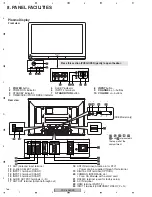
Page 168: ...nal 19 DIGITAL OUT terminal OPTICAL 20 COMMON INTERFACE slot For a CA Module with a smart card 21 RS232C terminal used for factory setup 22 AC IN terminal 23 HDMI terminal INPUT 3 24 INPUT 2 terminals COMPONENT VIDEO Y PB PR Front view 1 POWER button 2 POWER ON indicator 3 STANDBY indicator 4 TIMER SXE PIC OFF RXE indicator 5 SLEEP indicator 6 INPUT 4 terminals 7 STANDBY ON button 8 INPUT button 9...

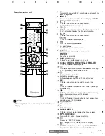
Page 169: ... Colour RED GREEN YELLOW BLUE TELETEXT mode Selects a page 11 TV External input mode Jumps to the Teletext subtitle page DTV input mode Turns subtitle on and off 12 Displays hidden characters 13 TV DTV SXE only Switches between the TV and DTV input modes 14 TV External input mode Selects the screen size TELETEXT mode Switches Teletext images full upper half lower half 15 TV External input mode Fre...

Page 170: ...40P Extension FFC Diagnosis of OB DIGITAL Assy at power on state Jig No Name Remarks Before shipping out the product be sure to clean the following positions by using the prescribed cleaning tools Position to be cleaned Cleaning tools Fans Cleaning paper GED 008 ...

Reviews: