PDP-LX5080D
93
5
6
7
8
5
6
7
8
C
D
F
A
B
E
N
N
I
F O R
E
T
M P
A
R
U R E
E
T
M
E
T
P 1
M
E
T
P 2
:
:
:
N 1
A
F
0
4
+
. 2
0
4
+
. 2
( C )
( C )
0
3
1
( A / D )
W
O
L
:
N 2
A
F
–
–
–
:
S E N S O R
–
B
2
0
3 ( A / D )
1
A
M
T I O
A
–
V 1
3
1
0 6 0
– N T V
H
E
–
B
1
5
10
15
16
1
5
10
15
20
25
30
35
40
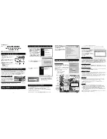
• Display/Meaning
TEMP1 : The temperature of the sensor on the panel side is displayed by the centigrade.
TEMP2 : The temperature conversion display is done with 10 bit the A/D input value of IF uCOM 90 pin (AN4). It is displayed by
both the centigrade (C) and 8 bit A/D value.
(Remark:When temperature (C) of the sensor becomes more than a specified temperature, the shutdown start of processing.)
FAN1
: The value of the FAN rotating state is displayed.
STOP: stopped, LOW: slow speed, HIGH: high speed.
FAN2
: The value of the rotation state of FAN is displayed.
During a rotation of FAN, 8bit D/A value output from 2 pin (DA0) of IF uCOM is displayed.
It is displayed with OFF during a stop (only for the FHD model).
B-SENSOR : The value that indicated the degree of brightness input into an Room light sensor is displayed.
AD value when the output of the Room light sensor was input into 89 pin (AN5) of IF uCOM is displayed.
However, the Regular A, D model is not displayed.
A present temperature and the FAN rotation are displayed.
If either [
] key or [
] key is pressed, the display data is refreshed.
6.2.1.4 TEMPERATURE
6.2.1.5 HOUR METER
Note:
The PANEL-side's HOUR METER/P-COUNT acquires information from the PANEL-side.
N
N
I
F O R
O
H
U R
E
M
E R
T
N
A
P
E L
S
/
E R I A L
P A N E L
P
C
-
O U N
S
R
E
I A L
T
C O U N T
A
M
T I O
A
–
V 1
3
1
0 6 0
– N T V
H
E
–
5
0 0 1
1 H
2 1 M
5
0 0
0 0
0
_ _ _ _ _ _ _ _ _ _ _ _ _ _ _
0
1
5
10
15
16
1
5
10
15
20
25
30
35
40
9
T I M E S
B
Meaning
Item Name
Display Example
Corresponding RS-232C Command
HOUR METER (PANEL)
PANEL
00151H 21M
QS3
POWER ON COUNTER
P-COUNT
00000095 TIMES
QS3
SYSTEM SERIAL
SERIAL
QS3
• Display/Meaning
Summary of Contents for KURO PDP-LX508D
Page 19: ...PDP LX5080D 19 5 6 7 8 5 6 7 8 C D F A B E ...
Page 20: ...PDP LX5080D 20 1 2 3 4 1 2 3 4 C D F A B E 4 BLOCK DIAGRAM 4 1 OVERALL WIRING DIAGRAM 1 2 ...
Page 22: ...PDP LX5080D 22 1 2 3 4 1 2 3 4 C D F A B E 4 2 OVERALL WIRING DIAGRAM 2 2 ...
Page 23: ...PDP LX5080D 23 5 6 7 8 5 6 7 8 C D F A B E ...
Page 159: ...PDP LX5080D 159 5 6 7 8 5 6 7 8 C D F A B E ...
Page 170: ...PDP LX5080D 170 1 2 3 4 1 2 3 4 C D F A B E 10 6 PANEL CHASSIS SECTION ...