background image

4

HTP-SB300

1

2

3

4

A

B

C

D

E

F

1

2

3

4

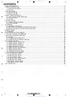
CONTENTS

 SAFETY INFORMATION..........................................................................................................................................................2
1. SERVICE PRECAUTIONS ....................................................................................................................................................5

1.1 NOTES ON SOLDERING ...............................................................................................................................................5
1.2 CAUTION 
........................................................................................................................................................................5

2. SPECIFICATIONS .................................................................................................................................................................6

2.1 SPECIFICATIONS ..........................................................................................................................................................6
2.2 PANEL FACILITIES.........................................................................................................................................................7

3. BASIC ITEMS FOR SERVICE............................................................................................................................................. 11

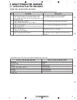
3.1 CHECK POINTS AFTER SERVICING.......................................................................................................................... 11
3.2 PCB LOCATIONS .........................................................................................................................................................12
3.3 JIGS LIST......................................................................................................................................................................13

4. BLOCK DIAGRAM...............................................................................................................................................................14

4.1 OVERALL WIRING DIAGRAM .....................................................................................................................................14
4.2 BLOCK DIAGRAM ........................................................................................................................................................16

5. DIAGNOSIS.........................................................................................................................................................................18

5.1 DIAGNOSIS FLOWCHART ..........................................................................................................................................18
5.2 DESCRIPTION OF WIRELESS PAIRING OPERATIONS ............................................................................................21
5.3 SPECIFICATIONS FOR THE PROTECTION CIRCUITS .............................................................................................23

6. SERVICE MODE .................................................................................................................................................................24
7. DISASSEMBLY....................................................................................................................................................................25
8. EACH SETTING AND ADJUSTMENT ................................................................................................................................28

8.1 HOW TO UPDATE THE FIRMWARE............................................................................................................................28

9. EXPLODED VIEWS AND PARTS LIST...............................................................................................................................34

9.1 PACKING ......................................................................................................................................................................34
9.2 EXTERIOR SECTION (Main unit) .................................................................................................................................36
9.3 EXTERIOR SECTION (Wireless subwoofer) ................................................................................................................38

10. SCHEMATIC DIAGRAM ....................................................................................................................................................40

10.1 PWB(PCB) ASSY (FRONT/KEY)................................................................................................................................40
10.2 PWB(PCB) ASSY (MAIN)(1/2) ....................................................................................................................................42
10.3 PWB(PCB) ASSY (MAIN)(2/2) ....................................................................................................................................44
10.4 WIRELESS AUDIO TX ASSY .....................................................................................................................................46
10.5 PWB(PCB) ASSY (SW MAIN/LED) ............................................................................................................................48
10.6 PWB(PCB) ASSY (SMPS) ..........................................................................................................................................50
10.7 WIRELESS AUDIO RX ASSY.....................................................................................................................................52
10.8 VOLTAGES and WAVEFORMS ..................................................................................................................................54

11. PCB CONNECTION DIAGRAM.........................................................................................................................................56

11.1 P.C.B SUB ASSY (INPUT) ..........................................................................................................................................56
11.2 PWB(PCB) ASSY (MAIN) ...........................................................................................................................................58
11.3 P.C.B SUB ASSY (HDMI) ............................................................................................................................................60
11.4 PWB(PCB) ASSY (SW MAIN/LED).............................................................................................................................62
11.5 PWB(PCB) ASSY (SMPS) ..........................................................................................................................................64
11.6 WIRELESS AUDIO RX ASSY .....................................................................................................................................66
11.7 WIRELESS AUDIO TX ASSY .....................................................................................................................................67

12. PCB PARTS LIST ..............................................................................................................................................................68

www. xiaoyu163. com

QQ 376315150

9

9

2

8

9

4

2

9

8

TEL 13942296513

9

9

2

8

9

4

2

9

8

0

5

1

5

1

3

6

7

3

Q

Q

TEL  13942296513  QQ  376315150  892498299 

TEL  13942296513  QQ  376315150  892498299 

http://www.xiaoyu163.com

http://www.xiaoyu163.com

Summary of Contents for HTP-SB300

Page 1: ...BAR SURROUND SYSTEM HTP SB300 THIS MANUAL IS APPLICABLE TO THE FOLLOWING MODEL S AND TYPE S Ask user to bring the Main unit and the Wireless subwoofer pair set together when servicing Model Type Power Requirement Remarks HTP SB300 SVYXCN5 AC 220 V to 240 V HTP SB300 CMXCN AC 120 V For details refer to Important Check Points for good servicing T ZZK DEC www xiaoyu163 com QQ376315150 9 9 2 8 9 4 2 9...

Page 2: ...ated for voltage wattage etc Replacement parts which have these special safety characteristics are identified in this Service Manual Electrical components having such features are identified by marking with a on the schematics and on the parts list in this Service Manual The use of a substitute replacement component which does not have the same safety characteristics as the PIONEER recommended rep...

Page 3: ... broken wires scratches melting etc on the coating of the power cord Damaged power cords may lead to fire accidents so please be sure that there are no damages If you find a damaged power cord please exchange it with a suitable one 9 There should be no spark traces or similar marks on the power plug When spark traces or similar marks are found on the power supply plug please check the connection a...

Page 4: ...T 34 9 1 PACKING 34 9 2 EXTERIOR SECTION Main unit 36 9 3 EXTERIOR SECTION Wireless subwoofer 38 10 SCHEMATIC DIAGRAM 40 10 1 PWB PCB ASSY FRONT KEY 40 10 2 PWB PCB ASSY MAIN 1 2 42 10 3 PWB PCB ASSY MAIN 2 2 44 10 4 WIRELESS AUDIO TX ASSY 46 10 5 PWB PCB ASSY SW MAIN LED 48 10 6 PWB PCB ASSY SMPS 50 10 7 WIRELESS AUDIO RX ASSY 52 10 8 VOLTAGES and WAVEFORMS 54 11 PCB CONNECTION DIAGRAM 56 11 1 P ...

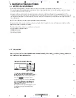
Page 5: ...lower wetting times and higher melting temperatures hard to melt easy to harden The following lead free solders are available as service parts Parts numbers of lead free solder GYP1006 1 0 in dia GYP1007 0 6 in dia GYP1008 0 3 in dia Pairing main unit and subwoofer 1 After you ve finished making the AC adapter and power cord connections press STANDBY ON on the main unit see above 2 Press on remote...

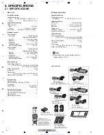
Page 6: ...Rated power output Subwoofer 100 W 100 Hz 4 Ω 10 Speaker section Enclosure Bass reflex type System 16 cm 1 way system Speakers 16 cm cone type x1 Impedance 4 Ω Frequency range 40 Hz to 1 000 Hz Maximum input power 100W Miscellaneous Power Requirements AC 220 V to 240 V 50 Hz 60 Hz SVYXCN5 Power Consumption 25 W In standby 1 W Dimensions 411 mm W x 181 mm H x 215 mm D Weight without package 4 3 kg ...

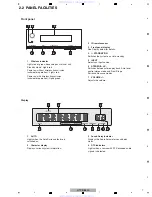
Page 7: ...stereo playback Auto level control stereo mode and Front Stage Surround Advance modes 7 VOLUME Adjusts the volume Display 1 Lights when the Auto Surround feature is switched on 2 Displays various system information 3 Displays the Audio Parameter sound delay status 4 AUTO Character display Sound Delay indicator DTS indicators Lights when a source with DTS encoded audio signals is detected STANDBY O...

Page 8: ...AL Lights when a digital audio signal is selected Blinks when a digital audio signal is not selected HDMI Lights when an HDMI signal is selected Blinks when an HDMI signal is not selected 8 Lights when DIMMER is set to off 9 Lights when the DIRECT or PURE DIRECT mode is switched on Subwoofer 1 Dolby Digital indicators ADV S SIGNAL SELECT indicators Dimmer indicator DIR Wireless indicator Standby m...

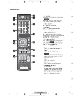
Page 9: ...ntrol of TV Also use to input a preset code allocated to the TV CONTROL button CH Use to select channels VOL Use to adjust the volume on your TV 7 Listening mode buttons AUTO DIRECT Switches between Auto surround mode Auto playback on page20 and Stream Direct playback Stream Direct playback bypasses the tone controls for the most accurate reproduction of a source assigned to the button Thus if you...

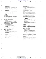
Page 10: ... options 11 MASTER VOLUME Use to set the listening volume 12 The main buttons etc are used to control a component after you have selected it using the input source buttons The controls above these buttons can be accessed after you have selected the corresponding input source button These buttons also function as described below DTV TV SVYXCN5 Switches between the DTV and analog TV input modes for ...

Page 11: ...gital audio playback Make the digital connections with a DVD player Each channel audio and operations must be normal Check surround playback Select Surround mode and check the multichannel operations via the DSP circuit Each channel audio and operations must be normal Check the video outputs Connect with a DVD player Video and operations must be normal Check the appearance of the product No scratc...

Page 12: ...L 1 PWB PCB ASSY MAIN 8952SB3004380 IL NSP 1 PWB PCB ASSY HDMI 7025HZ0902010 IL 2 P C B SUB ASSY HDMI 7028068701010 IL 1 WIRELESS AUDIO TX ASSY 8952SB3002510 IL 1 PWB PCB ASSY SW MAIN LED 8952SB3004270 IL 1 PWB PCB ASSY SMPS 8952SB3003790 IL 1 WIRELESS AUDIO RX ASSY 8952SB3003750 IL www xiaoyu163 com QQ376315150 9 9 2 8 9 4 2 9 8 TEL 13942296513 9 9 2 8 9 4 2 9 8 0 5 1 5 1 3 6 7 3 Q Q TEL 13942296...

Page 13: ...te SB update tool GGF1644 Firmware update Adhesive GYL 014 Silicon grease GEM1057 Jigs list www xiaoyu163 com QQ376315150 9 9 2 8 9 4 2 9 8 TEL 13942296513 9 9 2 8 9 4 2 9 8 0 5 1 5 1 3 6 7 3 Q Q TEL 13942296513 QQ 376315150 892498299 TEL 13942296513 QQ 376315150 892498299 http www xiaoyu163 com http www xiaoyu163 com ...
Page 14: ...N 2PIN CENTER SPEAKER LEFT SPEAKER 6ohm 12ohm 6PIN CP702 LD701 CP1 CN104 CN105 CN103 CP101 CP102 PN901 F PWB PCB ASSY SMPS 8952SB3003790 IL C P C B SUB ASSY HDMI 7028068701010 IL PWB PCB ASSY FRONT KE 8952SB3000490 IL A 2 2 E 1 2 B 1 2 www xiaoyu163 com QQ376315150 9 9 2 8 9 4 2 9 8 TEL 13942296513 9 9 2 8 9 4 2 9 8 0 5 1 5 1 3 6 7 3 Q Q TEL 13942296513 QQ 376315150 892498299 TEL 13942296513 QQ 37...

Page 15: ...07 D WIRELESS AUDIO TX ASSY 8952SB3002510 IL G WIRELESS AUDIO RX ASSY 8952SB3003750 IL PWB PCB ASSY FRONT KEY 8952SB3000490 IL A 1 2 FRONT KEY 0 IL PWB PCB ASSY SW MAIN LED 8952SB3004270 IL E 1 2 PWB PCB ASSY SW MAIN LED 8952SB3004270 IL E 2 2 PWB PCB ASSY MAIN 8952SB3004380 IL B 1 2 2 2 www xiaoyu163 com QQ376315150 9 9 2 8 9 4 2 9 8 TEL 13942296513 9 9 2 8 9 4 2 9 8 0 5 1 5 1 3 6 7 3 Q Q TEL 139...

Page 16: ...CK1002 JACK1004 IC101 IC104 Main unit Wireless subwoofer IC105 IC702 IC113 IC106 www xiaoyu163 com QQ376315150 9 9 2 8 9 4 2 9 8 TEL 13942296513 9 9 2 8 9 4 2 9 8 0 5 1 5 1 3 6 7 3 Q Q TEL 13942296513 QQ 376315150 892498299 TEL 13942296513 QQ 376315150 892498299 http www xiaoyu163 com http www xiaoyu163 com ...

Page 17: ...HDMI IN2 X1001 X1401 CN1001 CN1002 JACK1001 HDMI IN1 JACK1004 HDMI OUT www xiaoyu163 com QQ376315150 9 9 2 8 9 4 2 9 8 TEL 13942296513 9 9 2 8 9 4 2 9 8 0 5 1 5 1 3 6 7 3 Q Q TEL 13942296513 QQ 376315150 892498299 TEL 13942296513 QQ 376315150 892498299 http www xiaoyu163 com http www xiaoyu163 com ...
Page 18: ...e the PWB PCB Assy HDMI the check it Check the connection of MICOM communication port of PWB PCB Assy HDMI and PWB PCB Assy MAIN CSSK_MAIN SCDO_ MAIN SCDI_MAIN SUB_RESET SUBPDN MAIN_IRQ SUB_IRQ SUB_ON NG OK NG Replace the PWB PCB Assy HDMI the check it Check the waveforms of CP101 pin 4 HDMI_SD0 pin 5 HDMI_ SD1 pin 8 HDMI_LRCK pin 9 HDMI_BCK pin10 HDMI_MCLK Check audio output after HDMI input Note...

Page 19: ...IC122 or IC123 TAS5342A Replace the IC120 TAS5508 NG OK Replace the L102 L103 and L104 Check the I2S output waveform of IC104 CS8422 pins 27 FB110 28 FB109 29 FB108 and 31 FB107 Is the voltage of pin 32 R106 RESET of IC104 CS8422 High 3 3 V NG After opening R106 is the voltage of pin 32 of IC104 CS8422 High 3 3 V Replace the IC113 MICOM OK OK Replace the IC104 CS8422 Replace the IC104 CS8422 NG NG...

Page 20: ...ce the Q702 2SC2412K NG Replace the IC104 CS8422 NG OK Is the voltage of CP703 pin 3 GREEN High 3 3 V Replace the Connector Assy of 3 Pin LED PCB NG Replace the LD701 RED GREEN Dual LED OK Replace the JK102 Optical Jack Check the I2S waveforms of MOD101 pins 7 I2S_DATA 8 I2S_LRCK and 12 I2S_BCK NG NG OK OK Check the subwoofer audio output after OPTICAL input Note Input signal uses Dolby 5 1ch sour...

Page 21: ...acement has occurred in servicing etc The LED indications are as follows To enter the mode TX Sound Bar block 1 With TX in Power ON status simultaneously press the SHIFT key and the CH key for TV CONTROL on the remote control 2 The green LED blinks at intervals of 250 ms RX Subwoofer block 1 RX starts Re Pairing operation upon power on and continues it for 15 seconds at maximum The method of Pairi...

Page 22: ... paired with RX Condition 2 In a case where the module of TX or RX has been repaired or replaced The procedure of Re Pairing in a case where TX and RX have different IDs because of repair or replacement is as follows 1 Set TX to Re Pairing Mode The green LED of TX blinks at intervals of 250 ms for 1 minute 2 Disconnect the power to RX then connect it again The green LED of RX blinks at intervals o...

Page 23: ...ile the protection function is activated Therefore if no sound is output even if the LED is lit in green the protection function may have been activated 2 Over Temperature Protection MICOM Pin 88 In Normal Operation mode High In a case where the temperature of the AMP IC IC122 or IC123 becomes 125 C or higher Low The signal from Pin 14 of IC120 TAS5508 is set to low in order to mute the PWM output...

Page 24: ... information to be shown in this chapter www xiaoyu163 com QQ376315150 9 9 2 8 9 4 2 9 8 TEL 13942296513 9 9 2 8 9 4 2 9 8 0 5 1 5 1 3 6 7 3 Q Q TEL 13942296513 QQ 376315150 892498299 TEL 13942296513 QQ 376315150 892498299 http www xiaoyu163 com http www xiaoyu163 com ...
Page 25: ...el Front Grille Frame Catch Grille Frame Panel Front 3 Remove the five screws on the HDMI PCB 4 Remove the six screws on the MAIN PCB MAIN PCB HDMI PCB MAIN PCB HDMI PCB 3 3 4 4 4 3 4 4 4 3 3 Note The photo shows the state with the shield plate removed www xiaoyu163 com QQ376315150 9 9 2 8 9 4 2 9 8 TEL 13942296513 9 9 2 8 9 4 2 9 8 0 5 1 5 1 3 6 7 3 Q Q TEL 13942296513 QQ 376315150 892498299 TEL ...

Page 26: ...ard on side B If the spacer is damaged when removing the plate replace it with a new one Shield Plate MAIN PCB HDMI PCB MAIN PCB Shield Plate HDMI PCB SIDE A SIDE B www xiaoyu163 com QQ376315150 9 9 2 8 9 4 2 9 8 TEL 13942296513 9 9 2 8 9 4 2 9 8 0 5 1 5 1 3 6 7 3 Q Q TEL 13942296513 QQ 376315150 892498299 TEL 13942296513 QQ 376315150 892498299 http www xiaoyu163 com http www xiaoyu163 com ...
Page 27: ... four screws 1 Remove the ten screws 2 SUBWOOFER 3 Remove the four screws on the PCB AMP www xiaoyu163 com QQ376315150 9 9 2 8 9 4 2 9 8 TEL 13942296513 9 9 2 8 9 4 2 9 8 0 5 1 5 1 3 6 7 3 Q Q TEL 13942296513 QQ 376315150 892498299 TEL 13942296513 QQ 376315150 892498299 http www xiaoyu163 com http www xiaoyu163 com ...
Page 28: ...s How to enter exit To enter this mode during Normal Display mode simultaneously press the STEREO A L C key on the main unit and the Dimmer key on the remote control unit supplied with the HTP SB300 or the AV amp The display will return to the normal indication when no key operation is performed for 10 seconds If any other key is pressed during the version or FL TEST MODE display Normal Display mo...

Page 29: ...ain microcomputer as shown below PC with RS232C port RS 232C straight cable 9pin female 25pin male RS 232C Interface jig GGF1642 SB update tool GGF1644 Updating program FlashSta exe Firmware file mot file Necessary Tools Purpose Refer to this section when updating the firmware of each microcomputer is required by the service information etc MAIN and SUB microcomputer RS 232C Straight cable The pho...

Page 30: ...S 232C Straight cable Update terminals of the submicrocomputer Connect the connector of the FFC cable of the special tool to the Update terminals on the HDMI PCB www xiaoyu163 com QQ376315150 9 9 2 8 9 4 2 9 8 TEL 13942296513 9 9 2 8 9 4 2 9 8 0 5 1 5 1 3 6 7 3 Q Q TEL 13942296513 QQ 376315150 892498299 TEL 13942296513 QQ 376315150 892498299 http www xiaoyu163 com http www xiaoyu163 com ...
Page 31: ...ck the OK button 5 Select the firmware file mot file for updating each ucom and enter ID 1 Selection of upgrade file Note Do NOT download the firmware file for other ucom 2 Enter ID Enter ff in all field 3 Click the OK button to go to next step Procedures Note Do NOT disconnect the AC power cords of this unit and the PC during a downloading www xiaoyu163 com QQ376315150 9 9 2 8 9 4 2 9 8 TEL 13942...

Page 32: ...e Baud rate 38400 2 Upgrade MCU Check the E P R button 7 Finished 8 Unplug the AC cord 9 Disconnect the RS 232C interface special tool 10 Plug in the AC cord 11 Initialize the main unit www xiaoyu163 com QQ376315150 9 9 2 8 9 4 2 9 8 TEL 13942296513 9 9 2 8 9 4 2 9 8 0 5 1 5 1 3 6 7 3 Q Q TEL 13942296513 QQ 376315150 892498299 TEL 13942296513 QQ 376315150 892498299 http www xiaoyu163 com http www ...

Page 33: ...lay BRIGHTENS THE DISPLAY Resetting the main unit Use this procedure to reset all the system s settings to the factory default Use the front panel controls to do this 1 Switch the system on 2 While holding down the STEREO A L C button on the front panel press and hold the HDMI1 button on remote control for about two seconds 3 Unplug the power cord The system has been reset to the factory settings ...

Page 34: ...g be sure to use parts of identical designation Screws adjacent to b mark on product are used for disassembly For the applying amount of lubricants or glue follow the instructions in this manual In the case of no amount instructions apply as you think it appropriate WITH POWER CORD www xiaoyu163 com QQ376315150 9 9 2 8 9 4 2 9 8 TEL 13942296513 9 9 2 8 9 4 2 9 8 0 5 1 5 1 3 6 7 3 Q Q TEL 139422965...

Page 35: ... unit 8952SB3000130 IL NSP 23 Warranty Card See Contrast table 2 24 25 Pe Bag P Cord 8952SB3004230 IL 26 Poly Bag 8952SB3004240 IL 27 Carton Box See Contrast table 2 NSP 28 Serial Label S VRW2017 Mark No Description Part No Mark No Symbol and Description HTP SB300 SVYXCN5 HTP SB300 CMXCN 9 Remote Control AXD7576 8952SB3002630 IL Not used 9 Remote Control AXD7578 Not used 8952SB3002740 IL 10 AC Ada...

Page 36: ...ION Main unit B C D 1 2 A 2 2 A www xiaoyu163 com QQ376315150 9 9 2 8 9 4 2 9 8 TEL 13942296513 9 9 2 8 9 4 2 9 8 0 5 1 5 1 3 6 7 3 Q Q TEL 13942296513 QQ 376315150 892498299 TEL 13942296513 QQ 376315150 892498299 http www xiaoyu163 com http www xiaoyu163 com ...
Page 37: ...SB3000230 IL 28 Felt 8952SB3000240 IL 29 Felt 8952SB3000250 IL 30 Felt 8952SB3000270 IL NSP 31 Felt 8952SB3002870 IL 32 Felt 8952SB3002880 IL 33 Screw BBZ30P100FTB 34 Screw BBZ40P100FTB 35 Screw BBZ30P060FTB 36 Felt 8952SB3002970 IL 37 Felt 8952SB3004020 IL 38 Felt Shiled B 8952SB3004010 IL 39 Felt Shiled A 8952SB3002990 IL 40 Sheet 8952SB3002960 IL 41 Sheet 8952SB3002950 IL 42 Palte Top 8952SB300...

Page 38: ... Wireless subwoofer 1 2 F G E 2 2 E www xiaoyu163 com QQ376315150 9 9 2 8 9 4 2 9 8 TEL 13942296513 9 9 2 8 9 4 2 9 8 0 5 1 5 1 3 6 7 3 Q Q TEL 13942296513 QQ 376315150 892498299 TEL 13942296513 QQ 376315150 892498299 http www xiaoyu163 com http www xiaoyu163 com ...
Page 39: ...elt 8952SB3003150 IL 20 21 Cashmere 8952SB3003170 IL NSP 22 Hand Ins PWB PCB 8952SB3003320 IL 23 PWB PCB SMPS 8952SB3003790 IL 24 PWB PCB ASSY 8952SB3004270 IL SW MAIN LED 25 Screw 8952SB3004210 IL 26 Screw Bind Head 8952SB3003180 IL NSP 27 Felt 8952SB3003840 IL 28 Sheet See Contrast table 2 29 Sponge 8952SB3004260 IL 30 Screw TORX 8952SB3002910 IL 31 Cabinet Wood Assy 8952SB3004370 IL NSP 32 Net ...

Page 40: ...2 CN105 B 2 2 PWB PCB ASSY FRONT A 1 2 PWB PCB ASSY FRONT KEY 8952SB3000490 IL www xiaoyu163 com QQ376315150 9 9 2 8 9 4 2 9 8 TEL 13942296513 9 9 2 8 9 4 2 9 8 0 5 1 5 1 3 6 7 3 Q Q TEL 13942296513 QQ 376315150 892498299 TEL 13942296513 QQ 376315150 892498299 http www xiaoyu163 com http www xiaoyu163 com ...
Page 41: ...parts indicates the importance of the safety factor of the part Therefore when replacing be sure to use parts of identical designation The power supply is shown with the marked box www xiaoyu163 com QQ376315150 9 9 2 8 9 4 2 9 8 TEL 13942296513 9 9 2 8 9 4 2 9 8 0 5 1 5 1 3 6 7 3 Q Q TEL 13942296513 QQ 376315150 892498299 TEL 13942296513 QQ 376315150 892498299 http www xiaoyu163 com http www xiaoy...

Page 42: ... C PWB PCB ASSY MAIN 8952SB3004380 IL B 1 2 8 7 D C 1 2 B A E F www xiaoyu163 com QQ376315150 9 9 2 8 9 4 2 9 8 TEL 13942296513 9 9 2 8 9 4 2 9 8 0 5 1 5 1 3 6 7 3 Q Q TEL 13942296513 QQ 376315150 892498299 TEL 13942296513 QQ 376315150 892498299 http www xiaoyu163 com http www xiaoyu163 com ...

Page 43: ...F B 1 2 B 2 2 www xiaoyu163 com QQ376315150 9 9 2 8 9 4 2 9 8 TEL 13942296513 9 9 2 8 9 4 2 9 8 0 5 1 5 1 3 6 7 3 Q Q TEL 13942296513 QQ 376315150 892498299 TEL 13942296513 QQ 376315150 892498299 http www xiaoyu163 com http www xiaoyu163 com ...

Page 44: ...8952SB3004380 IL B 2 2 3 9 11 Various setting data are stored in EEPROM IC114 M24C16 www xiaoyu163 com QQ376315150 9 9 2 8 9 4 2 9 8 TEL 13942296513 9 9 2 8 9 4 2 9 8 0 5 1 5 1 3 6 7 3 Q Q TEL 13942296513 QQ 376315150 892498299 TEL 13942296513 QQ 376315150 892498299 http www xiaoyu163 com http www xiaoyu163 com ...

Page 45: ...C C C SW Audio Signal Route SubWoofer ch SW CENTER SPEAKER LEFT SPEAKER RIGHT SPEAKER 12 I 6 5 4 10 G G G G H H H H H www xiaoyu163 com QQ376315150 9 9 2 8 9 4 2 9 8 TEL 13942296513 9 9 2 8 9 4 2 9 8 0 5 1 5 1 3 6 7 3 Q Q TEL 13942296513 QQ 376315150 892498299 TEL 13942296513 QQ 376315150 892498299 http www xiaoyu163 com http www xiaoyu163 com ...

Page 46: ...1 B 2 2 D WIRELESS AUDIO TX ASSY 8952SB3002510 IL www xiaoyu163 com QQ376315150 9 9 2 8 9 4 2 9 8 TEL 13942296513 9 9 2 8 9 4 2 9 8 0 5 1 5 1 3 6 7 3 Q Q TEL 13942296513 QQ 376315150 892498299 TEL 13942296513 QQ 376315150 892498299 http www xiaoyu163 com http www xiaoyu163 com ...
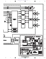
Page 47: ... D E F D www xiaoyu163 com QQ376315150 9 9 2 8 9 4 2 9 8 TEL 13942296513 9 9 2 8 9 4 2 9 8 0 5 1 5 1 3 6 7 3 Q Q TEL 13942296513 QQ 376315150 892498299 TEL 13942296513 QQ 376315150 892498299 http www xiaoyu163 com http www xiaoyu163 com ...

Page 48: ...MAIN PWB PCB ASSY SW MAIN LED 8952SB3004270 IL E 1 2 CN1 G SW SW www xiaoyu163 com QQ376315150 9 9 2 8 9 4 2 9 8 TEL 13942296513 9 9 2 8 9 4 2 9 8 0 5 1 5 1 3 6 7 3 Q Q TEL 13942296513 QQ 376315150 892498299 TEL 13942296513 QQ 376315150 892498299 http www xiaoyu163 com http www xiaoyu163 com ...

Page 49: ...1 F SW Audio Signal Route SubWoofer ch SW SW www xiaoyu163 com QQ376315150 9 9 2 8 9 4 2 9 8 TEL 13942296513 9 9 2 8 9 4 2 9 8 0 5 1 5 1 3 6 7 3 Q Q TEL 13942296513 QQ 376315150 892498299 TEL 13942296513 QQ 376315150 892498299 http www xiaoyu163 com http www xiaoyu163 com ...

Page 50: ...B ASSY SMPS F NEUTRAL LlVE www xiaoyu163 com QQ376315150 9 9 2 8 9 4 2 9 8 TEL 13942296513 9 9 2 8 9 4 2 9 8 0 5 1 5 1 3 6 7 3 Q Q TEL 13942296513 QQ 376315150 892498299 TEL 13942296513 QQ 376315150 892498299 http www xiaoyu163 com http www xiaoyu163 com ...

Page 51: ...YPE AND RATINGS OF FUSE CAUTION CAUTION FOR CONTINUED PROTECTION AGAINST RISK OF FIRE REPLACE ONLY WITH SAME TYPE NO ICP N25 MFD BY ROHM CO LTD FOR F903 www xiaoyu163 com QQ376315150 9 9 2 8 9 4 2 9 8 TEL 13942296513 9 9 2 8 9 4 2 9 8 0 5 1 5 1 3 6 7 3 Q Q TEL 13942296513 QQ 376315150 892498299 TEL 13942296513 QQ 376315150 892498299 http www xiaoyu163 com http www xiaoyu163 com ...

Page 52: ...IRELESS AUDIO RX ASSY 8952SB3003750 IL MOD701 E www xiaoyu163 com QQ376315150 9 9 2 8 9 4 2 9 8 TEL 13942296513 9 9 2 8 9 4 2 9 8 0 5 1 5 1 3 6 7 3 Q Q TEL 13942296513 QQ 376315150 892498299 TEL 13942296513 QQ 376315150 892498299 http www xiaoyu163 com http www xiaoyu163 com ...

Page 53: ... D E F G www xiaoyu163 com QQ376315150 9 9 2 8 9 4 2 9 8 TEL 13942296513 9 9 2 8 9 4 2 9 8 0 5 1 5 1 3 6 7 3 Q Q TEL 13942296513 QQ 376315150 892498299 TEL 13942296513 QQ 376315150 892498299 http www xiaoyu163 com http www xiaoyu163 com ...

Page 54: ...V2 1 2 V IC117 2 VCC33 3 3 V IC121 2 VCC12 12 V C206 MVCC33 MICOM 3 3 V DC IN CN104 1 2 FL FL 4 3 V CN104 3 VEE 30V CN104 5 MVCC33 3 3 V C235 VCC5 5 V 1 3 4 5 6 12 2 7 8 9 10 11 B PWB PCB ASSY MAIN SIDE A www xiaoyu163 com QQ376315150 9 9 2 8 9 4 2 9 8 TEL 13942296513 9 9 2 8 9 4 2 9 8 0 5 1 5 1 3 6 7 3 Q Q TEL 13942296513 QQ 376315150 892498299 TEL 13942296513 QQ 376315150 892498299 http www xiao...

Page 55: ...PWM output MOD101 8 I2S_LRCK Subwoofer A B C D E F H I R338 R339 R340 R341 R342 R343 L L R R C C PWM output G B PWB PCB ASSY MAIN SIDE A B PWB PCB ASSY MAIN SIDE B www xiaoyu163 com QQ376315150 9 9 2 8 9 4 2 9 8 TEL 13942296513 9 9 2 8 9 4 2 9 8 0 5 1 5 1 3 6 7 3 Q Q TEL 13942296513 QQ 376315150 892498299 TEL 13942296513 QQ 376315150 892498299 http www xiaoyu163 com http www xiaoyu163 com ...

Page 56: ...A 1 2 NOTE FOR PCB DIAGRAMS 1 The parts mounted on this PCB include all necessary parts for several destinations For further information for respective desti nations be sure to check with the sche matic diagram Capacitor Connector P C Board Chip Part SIDE A SIDE B 2 View point of PCB diagrams www xiaoyu163 com QQ376315150 9 9 2 8 9 4 2 9 8 TEL 13942296513 9 9 2 8 9 4 2 9 8 0 5 1 5 1 3 6 7 3 Q Q TE...

Page 57: ...Y FRONT KEY PWB PCB ASSY KEY A 2 2 PWB PCB ASSY FRONT A 1 2 SIDE B SIDE B www xiaoyu163 com QQ376315150 9 9 2 8 9 4 2 9 8 TEL 13942296513 9 9 2 8 9 4 2 9 8 0 5 1 5 1 3 6 7 3 Q Q TEL 13942296513 QQ 376315150 892498299 TEL 13942296513 QQ 376315150 892498299 http www xiaoyu163 com http www xiaoyu163 com ...

Page 58: ...5 IC Q Q105 Q104 Q107 Q109 Q108 IC112 IC101 IC106 IC110 IC107 IC109 IC124 IC117 IC116 IC121 Q102 Q103 B PWB PCB ASSY MAIN B PWB PCB ASSY MAIN SIDE A SIDE B www xiaoyu163 com QQ376315150 9 9 2 8 9 4 2 9 8 TEL 13942296513 9 9 2 8 9 4 2 9 8 0 5 1 5 1 3 6 7 3 Q Q TEL 13942296513 QQ 376315150 892498299 TEL 13942296513 QQ 376315150 892498299 http www xiaoyu163 com http www xiaoyu163 com ...

Page 59: ...4 CP106 CP107 RIGHT SPEAKER MOD101 MOD101 D CN1 Q107 Q109 Q108 IC121 IC113 IC115 IC114 IC118 IC119 IC120 IC122 IC123 Q106 SIDE A SIDE B www xiaoyu163 com QQ376315150 9 9 2 8 9 4 2 9 8 TEL 13942296513 9 9 2 8 9 4 2 9 8 0 5 1 5 1 3 6 7 3 Q Q TEL 13942296513 QQ 376315150 892498299 TEL 13942296513 QQ 376315150 892498299 http www xiaoyu163 com http www xiaoyu163 com ...

Page 60: ...000 1S B CP102 CN1002 B CP101 CN1001 IC IC1003 IC1001 IC1002 Q SIDE A SIDE A C P C B SUB ASSY HDMI www xiaoyu163 com QQ376315150 9 9 2 8 9 4 2 9 8 TEL 13942296513 9 9 2 8 9 4 2 9 8 0 5 1 5 1 3 6 7 3 Q Q TEL 13942296513 QQ 376315150 892498299 TEL 13942296513 QQ 376315150 892498299 http www xiaoyu163 com http www xiaoyu163 com ...

Page 61: ...Q1003 Q1004 Q1002 Q1201 Q1405 Q1001 Q SIDE B SIDE B C P C B SUB ASSY HDMI www xiaoyu163 com QQ376315150 9 9 2 8 9 4 2 9 8 TEL 13942296513 9 9 2 8 9 4 2 9 8 0 5 1 5 1 3 6 7 3 Q Q TEL 13942296513 QQ 376315150 892498299 TEL 13942296513 QQ 376315150 892498299 http www xiaoyu163 com http www xiaoyu163 com ...

Page 62: ...PN701 G CN1 MOD701 F PN901 CP702 IC IC702 Q701 Q702 IC701 IC703 Q SIDE A SIDE A E PWB PCB ASSY SW MAIN LED PWB PCB ASSY SW MAIN E 1 2 PWB PCB ASSY LED E 2 2 www xiaoyu163 com QQ376315150 9 9 2 8 9 4 2 9 8 TEL 13942296513 9 9 2 8 9 4 2 9 8 0 5 1 5 1 3 6 7 3 Q Q TEL 13942296513 QQ 376315150 892498299 TEL 13942296513 QQ 376315150 892498299 http www xiaoyu163 com http www xiaoyu163 com ...

Page 63: ...PCB ASSY SW MAIN LED PWB PCB ASSY SW MAIN E 1 2 PWB PCB ASSY LED E 2 2 www xiaoyu163 com QQ376315150 9 9 2 8 9 4 2 9 8 TEL 13942296513 9 9 2 8 9 4 2 9 8 0 5 1 5 1 3 6 7 3 Q Q TEL 13942296513 QQ 376315150 892498299 TEL 13942296513 QQ 376315150 892498299 http www xiaoyu163 com http www xiaoyu163 com ...

Page 64: ...702 PN901 PN903 IC IC941 IC902 IC922 IC901 Q902 Q904 Q903 Q901 Q SIDE A SIDE A F PWB PCB ASSY SMPS NEUTRAL LlVE www xiaoyu163 com QQ376315150 9 9 2 8 9 4 2 9 8 TEL 13942296513 9 9 2 8 9 4 2 9 8 0 5 1 5 1 3 6 7 3 Q Q TEL 13942296513 QQ 376315150 892498299 TEL 13942296513 QQ 376315150 892498299 http www xiaoyu163 com http www xiaoyu163 com ...

Page 65: ...IDE B SIDE B F PWB PCB ASSY SMPS www xiaoyu163 com QQ376315150 9 9 2 8 9 4 2 9 8 TEL 13942296513 9 9 2 8 9 4 2 9 8 0 5 1 5 1 3 6 7 3 Q Q TEL 13942296513 QQ 376315150 892498299 TEL 13942296513 QQ 376315150 892498299 http www xiaoyu163 com http www xiaoyu163 com ...

Page 66: ...SIDE A SIDE A SIDE B SIDE B WIRELESS AUDIO RX ASSY G WIRELESS AUDIO RX ASSY G www xiaoyu163 com QQ376315150 9 9 2 8 9 4 2 9 8 TEL 13942296513 9 9 2 8 9 4 2 9 8 0 5 1 5 1 3 6 7 3 Q Q TEL 13942296513 QQ 376315150 892498299 TEL 13942296513 QQ 376315150 892498299 http www xiaoyu163 com http www xiaoyu163 com ...

Page 67: ...SIDE A SIDE A SIDE B SIDE B D WIRELESS AUDIO TX ASSY D WIRELESS AUDIO TX ASSY www xiaoyu163 com QQ376315150 9 9 2 8 9 4 2 9 8 TEL 13942296513 9 9 2 8 9 4 2 9 8 0 5 1 5 1 3 6 7 3 Q Q TEL 13942296513 QQ 376315150 892498299 TEL 13942296513 QQ 376315150 892498299 http www xiaoyu163 com http www xiaoyu163 com ...

Page 68: ...AUDIO TX ASSY 8952SB3002510 IL 1 PWB PCB ASSY SW MAIN LED 8952SB3004270 IL 1 PWB PCB ASSY SMPS 8952SB3003790 IL 1 WIRELESS AUDIO RX ASSY 8952SB3003750 IL Mark No Description Part No A PWB PCB ASSY FRONT KEY SEMICONDUCTORS IC 1 8952SB3000690 IL IC 9001 RMC1 8952SB3000560 IL Q 1 8952SB3000860 IL Q 2 3 6 8952SB3000850 IL Q 4 5 8952SB3000840 IL D 1 LD1 8952SB3000590 IL MISCELLANEOUS L 1 FILTER CIRC EM...

Page 69: ...1320 IL CN107 WAFER 8952SB3001310 IL CN201 CONNECTOR 8952SB3001350 IL CN202 CONNECTOR 8952SB3001360 IL CN9101 MOD101 CONNECTOR 8952SB3001240 IL CN9102 PN102 CONNECTOR 8952SB3001230 IL CONNECTOR 8952SB3000450 IL CONNECTOR 8952SB3000460 IL C P C B SUB ASSY HDMI SEMICONDUCTORS IC 1003 J020303020030 IL IC 1002 J040913400030 IL IC 1001 J040923300030 IL IC 1005 J126111710011 IL IC 1004 J126111712040 IL ...

Reviews: