56
HTP-SB300
1
2
3
4
A
B
C
D
E
F
1
2
3
4
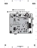
11. PCB CONNECTION DIAGRAM
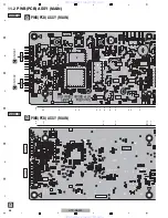
11.1 P.C.B SUB ASSY (INPUT)
A
A
Rev 4.0
HTP-SB300
2009.09.23
HTP-SB300 2009.09.23
Rev 4.0
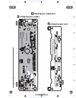
[Pioneer ] SOUND BAR [FRONT]
B
CN105
B
CN103
CP501
CP2
B
CN104
CP1
SIDE A
SIDE A
A
PWB(PCB) ASSY (FRONT/KEY)
PWB(PCB) ASSY (KEY)
A
2/2
PWB(PCB) ASSY
(FRONT)
A
1/2
NOTE FOR PCB DIAGRAMS :
1. The parts mounted on this PCB include all
necessary parts for several destinations.
For further information for respective desti-
nations, be sure to check with the sche-
matic diagram.
Capacitor
Connector
P.C.Board
Chip Part
SIDE A
SIDE B
2. View point of PCB diagrams.
www. xiaoyu163. com
QQ 376315150
9
9
2
8
9
4
2
9
8
TEL 13942296513
9
9
2
8
9
4
2
9
8
0
5
1
5
1
3
6
7
3
Q
Q
TEL 13942296513 QQ 376315150 892498299
TEL 13942296513 QQ 376315150 892498299

