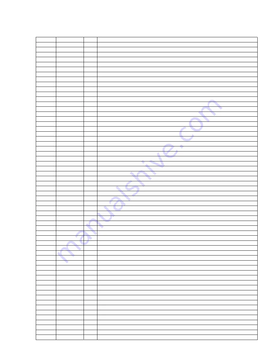
Pin No.
Pin Name
I/O
Function and Operation
68
LOADSW
I
3L:Loading SW input
69
POS
O
3L:Position sense output
70
RES
I
3L:Reverse sense input
71
NES
I
3L:Normal sense input
72
SC2
I
3L:Sub motor control input 2
73
SC1
I
3L:Sub motor control input 1
74
CM
I
3L:Capstan motor control input
75
STBY
O
3L:Drive IC control output
76
NC
Not used
77
ILMPW
O
Illumination power supply control output
78
NC
Not used
79
MUTE
O
Mute output
80
SYSPW
O
System power supply control output
81
DALMON
O
For consumption low-current output
82
EMUTE
I
DOLPHIN Mute input
83–86
NC
Not used
87
ASENBO
O
Slave power supply control output
88
IPPW
O
IP-BUS:Driver power supply output
89
TX
O
IP-BUS:Data output
90
RX
I
IP-BUS:Data input
91–94
NC
Not used
95
XRST
O
CD:LSI reset output
96
BSENS
I
Back up power sense input
97
ASENS
I
ACC power sense input
98
ISENS
I
Illumination sense input
99
DSENS
I
Grille detach sense input
100
RCK
I
RDS:Clock input
101
LDET
I
RDS:PLL lock sense detect input
102
NC
Not used
103
AVDD
A/D converter power supply
104
AVSS
A/D converter ground potential
105
AVREF
A/D converter standard voltage
106
SL
I
TUN:Signal level input
107
NL1
I
RDS:Noise level input
108
SDBW
I
RDS:SD input at NF
109,110
NC
Not used
111
DSCSNS
I
CD:Disc detect input
112
VDSENS
I
CD:VD voltage sense input
113
TEMP
CD:Temperature sense
114–116
NC
Not used
117
TELIN
I
TEL mute signal input
118
TESTIN
I
Test program mode input
119–122
XPI0-3
I/O
CD:LSI data input/output 0-3
123
XPCK
O
CD:LSI clock output
124
XCE
O
CD:LSI chip enable output
125,126
TUNPCE2,1
O
PLL:Chip enable output 2,1
127
TUNPDI
I
PLL:Data input
128
TUNPDO
O
PLL:Data output
129
TUNPCK
O
PLL:Clock output
130–134
NC
Not used
135
VSS
GND
136
VDD
Power supply
137
SWVDD
O
Grille:Power supply control output
138
DPDT
O
Grille:Data output
139
KEYDT
I
Grille:Data input
140
IFCK
O
DSP controller shift clock output
141
IFDI
I
DSP controller data input
142
IFDO
O
DSP controller data output
143
RDS57K
I
RDS:57kHz pulse count input
144
PEE
O
Beep tone output
87
FH-P4000,P4000R
Summary of Contents for FH-P4000
Page 12: ...12 FH P4000 P4000R 2 5 CD MECHANISM MODULE C ...
Page 14: ...14 FH P4000 P4000R 2 6 CASSETTE MECHANISM MODULE E D ...
Page 31: ...31 FH P4000 P4000R 5 6 7 8 5 6 7 8 D C B A 47K B KEYBOARD UNIT A CN801 B ...
Page 32: ...32 FH P4000 P4000R 1 2 3 4 1 2 3 4 D C B A 3 5 KEYBOARD UNIT FH P4000R X1N EW PE5234B A B ...
Page 33: ...33 FH P4000 P4000R 5 6 7 8 5 6 7 8 D C B A 47K B KEYBOARD UNIT A CN801 B ...
Page 42: ...IC Q A AUDIO AMP UNIT A 42 FH P4000 P4000R 1 2 3 4 1 2 3 4 D C B A ...
Page 43: ...A FRONT 43 FH P4000 P4000R 5 6 7 8 5 6 7 8 D C B A SIDE B ...
Page 45: ...45 FH P4000 P4000R 1 2 3 4 1 2 3 4 D C B A IC Q KEYBOARD UNIT B B CN801 A SIDE B ...
Page 47: ...47 FH P4000 P4000R 1 2 3 4 1 2 3 4 D C B A SIDE B CONTROL UNIT C C CLAMP 8EJ ...
Page 71: ...71 FH P4000 P4000R Grating waveform Ech Xch 20mV div AC Fch Ych 20mV div AC 45 0 75 60 30 90 ...


