


CX-692
14
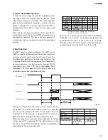
1.5.4 SPINDLE SERVO SYSTEM
DVD
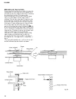
Fig. 15 shows the block diagram of the spindle servo
system when the DVD is being driven. 3 different types
of servo motors are available for the spindle servo
system. Namely, the FG servo wherewith the spindle
motor will be so controlled that the intervals of the FG
pulses being input from the spindle motor may become
the specified value, the roughing servo wherewith the
spindle servo will be so controlled that the maximum
inversion intervals (maximum runs) of the RF signals
being played back from the disc may become 14T
(formally, combination of "14T-4T") and the
speed/phase servo wherewith the spindle motor will be
so controlled that the VCO clock frequency may become
the same frequency as that of the maser clock and, at
the same time, the clock phase can be synchronized.
* Outline of the FG servo
The FG servo is a servo which works to control the
spindle revolution to the desired revolution rate by
monitoring the FG pulse cycle from the FG pluses being
generated by the spindle motor and by providing target
value for the FG pulse cycle from an external source
(CPU). The master clock (hereafter called the "FCLK")
should be 1/4 divisions of the MCK (when the MCK =
27MHz., the FCLK = 6.75MHz.) and the number of bit of
the counter to detect the FG pulse cycle should be 16bit.
* Outline of the roughing servo
The roughing servo is works to control the spindle so
that the maximum inversion interval (maximum run)
may become 14T when driving a DVD disk. For the
roughing servo, MCK = RCLK works as the master clock.
* Outline of the speed servo
The speed servo works to control the spindle so that the
frequency of the MCK may become the same as that of
the VCO clock extracted from the RF signals. With the
speed servo, the VCLK which is 23 divisions of the MCK
works as the master clock.
* Outline of the phase servo
The phase servo works to control the spindle so that the
phase of the MCK and VCO may coincide.
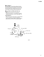
* Spindle lock
Spindle lock is a movement to shift from roughing
servo to the speed/phase servo. The RLOCK and FLOCK
being generated from the demodulator section are
signals indicating the detection state of the frame sink.
With these signals, window is being provided at each
frame cycle to determine if frame sink (14T - 4T) exists
in there. With the FLOCK, the frame sink detection
window width is
±
5 as against the VCO and with the
RLOCK, the frame sink detection window width is
±
48
as against the VCO. When the frame sink is detected 3
times in succession, the LOCK state will be called for
and when the frame sink is not detected 7 times
continuously, the UNLOCK state will be called for. The
RLOCK and FLOCK work to make sampling at the
frequency of MCK/211 at the spindle section to use for
detection of spindle lock. At the spindle lock selecting
section, once the RLOCK is detected, the next sampling
lock will call for the spindle lock state. Under the
spindle lock state, if FLOCK sampling will not be made
for 128 times continuously, the UNLOCK state will be
called for. When the MCK is 27MHz, the sampling
frequency will be: 27MHz/211 = 13kHz. The duration
that FLOCK sampling will not be made for 128 times
continuously equals to a time of 10ms.
CD
Fig. 15 shows the block diagram of the spindle servo
system when the CD is being driven. The disc motor
will be controlled by use of the frame sink signal (SFSY:
7.35kHz under normal speed) extracted from the RF
signals by the servo DSP (TC9461F), and the phase
comparison singles and frequency detection signals
from a crystal type clock. The control signals will be
output through the DMO pins in triplicate levels (AVSS,
VREF and 2VREF) after PWM modulation. The SFSY
signals will be output through the SFSY pin.
Meanwhile, the carrier frequency for the PWM
modulated signals is at 88.2kHz, which synchronizes
with the clock for the disc turning system.
MY-CHIP(Table of respective port states)
Spindle state
FPWM
RERR
VPWM
PPWM
IC701-Pin159
IC701-Pin158
IC701-Pin160
IC701-Pin161
In standstill
DUTY 50%
HiZ
HiZ
HiZ
In accelerating
DUTY 99%
HiZ
HiZ
HiZ
state
In locked state
DUTY 50%
HiZ
DUTY 50%,approx. DUTY 50%,approx.
In decelerating
DUTY 0%
HiZ
HiZ
HiZ
state


