12
CX-692
1.5.3 CARRIAGE SERVO
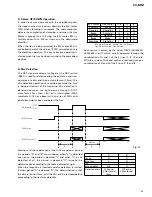
To drive the carriage servo, the outputs from the
tracking equalizer will be input into the carriage
equalizer and, after adding a certain gain to the low
frequency component (lens position data), drive signals
will be output from the servo DSP (IC401:TC9461F).
More specifically, when the lens offset reaches a certain
level while being played back, it becomes necessary to
move the whole pickup unit toward the forward
direction and the equalizer gains are so preset that
higher voltage than the carriage motor starting voltage
may be outputted at that time.
Meanwhile, as the actual movements, a certain
threshold level for the equalizer output is being preset
inside the servo DSP and the drive voltage will be
outputted from the servo DSP only when the equalizer
output level exceeds the threshold level.
The above movement works to suppress the power
consumption. Also, depending on the eccentricity of
the disc, the equalizer output voltages may cross the
threshold level for some times before the whole pickup
starts movement. In such case, the output waveform
of the drive voltage coming from the servo DSP will
become pulse form.
44
T EQ.
C EQ.
TE
IC401
TC9461F
TRO
41
48
2
3
1
M
IC304
BA6797FM
DRIVER
4
3
1
2
CARRIAGE
MOTOR
Carriage Servo Circuit
Fig. 13


