52
CDX-FM657
-
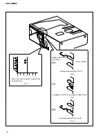
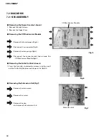
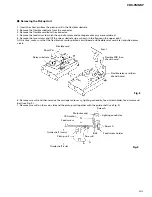
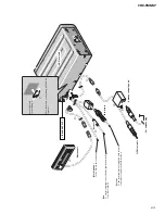
Removing the Extension Unit(Fig.7)
Remove the two screws.
Remove the screw.
Remove the claw
and remove the Extension Unit.
-
Removing the Upper Case(not shown)
1. Remove the night screws.
2. Remove the Upper Case.
-
Removing the CD Mechanism Module
Remove the four dampers(Fig.5).
Disconnect the connector(Fig.5).
Remove the two springs(Fig.5).
Disconnect the connector and then remove the
CD Mechanism Module(Fig.6).
-
Removing the Grille Unit(not shown)
1. Press the two tabs indicated by arrows and then pull
out the Grille Unit(Exterior section parts list No.50).
Fig.7
CD Mechanism Module
Fig.5
Fig.6
7.2 DIAGNOSIS
7.2.1 DISASSEMBLY
Extension Unit
Summary of Contents for CDX-FM657
Page 7: ...7 CDX FM657 2 2 EXTERIOR ...
Page 10: ...10 CDX FM657 2 3 CD MECHANISM MODULE ...
Page 16: ...16 CDX FM657 1 2 3 4 1 2 3 4 D C B A A 1 2 SYSTEM CONTROLLER LOUT AAGND ROUT GND VD A 2 2 ...
Page 17: ...17 CDX FM657 5 6 7 8 5 6 7 8 D C B A GGC1257 SRM2B256SLTMX70 B CN201 SRAM IP BUS DRIVER A2 2 ...
Page 21: ...21 CDX FM657 ...
Page 24: ...24 CDX FM657 1 2 3 4 1 2 3 4 D C B A 1 2 3 4 1 2 3 3 3 ANTENNA SELECT UNIT F 4 A CN401 F B ...
Page 29: ...29 CDX FM657 D C B A B EXTENSION UNIT B SIDE B 1 2 3 4 1 2 3 4 ...
Page 40: ...40 CDX FM657 Grating waveform 45 0 75 60 30 90 Echt Xch 20mV div AC Fcht Ych 20mV div AC ...
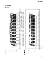
Page 51: ...51 CDX FM657 7 1 2 DISPLAY CAW1514 COMMON SEGMENT ...
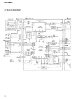
Page 60: ...60 CDX FM657 7 3 BLOCK DIAGRAM A C D E B ...
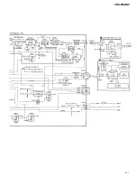
Page 61: ...61 CDX FM657 F G ...


