
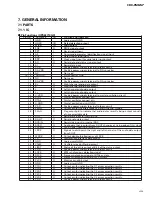


57
CDX-FM657
Code
Class
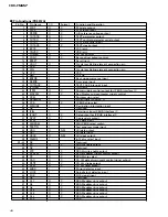
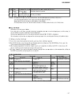
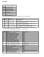
Displayed error code Description of the code and potential cause(s)
70
Mecha-
An error upon
Elevation time has time out.
nism
elevation
80
Mecha-
An error with an em- No disc is available.
nism
pty magazine inserted
Remarks: Unreadable TOC does not constitute an error. An intended operation continues in this case.
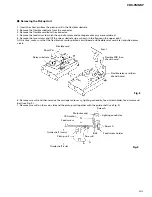
A newly designed head unit must conform to the example given above.
Upper digits of an error code are subdivided as shown below:
1x: Setup relevant errors, 3x: Search relevant errors, 3x: Search relevant errors, Ax: Other errors.
-
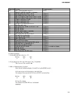
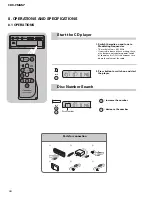
New Test Mode
M-CD plays the same way as before.
If an error such as off focus, spindle unlocking, unreadable sub-code, or sound skipping occurs after setup, its
cause and time occurred (in absolute time) are displayed.
During setup, operational status of the control software (internal RAM: CPOINT) is displayed.
These displays and functions are prepared for enhancing aging in the servicing and efficiency of trouble analysis.
(1) Shifting to the New Test Mode
1
Turn on the current test mode by starting the reset from the 4 and 6 keys together.
2
Select M-CD for the source through the specified procedure including use of the [SOURCE] key. Then, press the
12 key while maintaining the regulator turned off.
3
After the above operations, the new test mode remains on irrespective of whether the M-CD is turned on or off.
You can reset the new test mode by turning on the reset start.
* With some products, the new test mode can be reset through the same operations as that employed for shifting to
the STBY mode (while maintaining the Acc turned off).
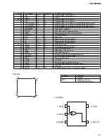
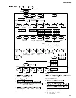
(2) Key Correspondence
Key
Test mode
New test mode
(Example)
Power Off
Power On
In-play
Error Production
BAND
To power on
To power off
–
Time/Err.No. switching
(offset adjustment performed)
UP
–
FWD-Kick
FF/TR+
–
DOWN
–
REV-Kick
REV/TR-
–
7
–
T.Close (AGC performed)
Scan
–
/parameter display switching
8
RF AMP gain switching
Parameter display switching
Mode
–
/T.BAL adjustment/T.Open
9
To power on
F.Close/RF AGC/F.T.AGC
–
–
(offset adjustment not performed)
10
–
F.Open
–
–
11
–
Jump Off
–
–
12
–
F.Mode switching
Auto/Manu T.No./Time switching
/T.Close (no AGC)/Jump switching
Summary of Contents for CDX-FM657
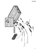
Page 7: ...7 CDX FM657 2 2 EXTERIOR ...
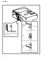
Page 10: ...10 CDX FM657 2 3 CD MECHANISM MODULE ...
Page 16: ...16 CDX FM657 1 2 3 4 1 2 3 4 D C B A A 1 2 SYSTEM CONTROLLER LOUT AAGND ROUT GND VD A 2 2 ...
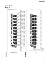
Page 17: ...17 CDX FM657 5 6 7 8 5 6 7 8 D C B A GGC1257 SRM2B256SLTMX70 B CN201 SRAM IP BUS DRIVER A2 2 ...
Page 21: ...21 CDX FM657 ...
Page 24: ...24 CDX FM657 1 2 3 4 1 2 3 4 D C B A 1 2 3 4 1 2 3 3 3 ANTENNA SELECT UNIT F 4 A CN401 F B ...
Page 29: ...29 CDX FM657 D C B A B EXTENSION UNIT B SIDE B 1 2 3 4 1 2 3 4 ...
Page 40: ...40 CDX FM657 Grating waveform 45 0 75 60 30 90 Echt Xch 20mV div AC Fcht Ych 20mV div AC ...
Page 51: ...51 CDX FM657 7 1 2 DISPLAY CAW1514 COMMON SEGMENT ...
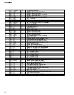
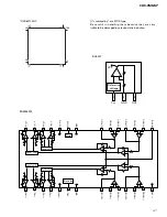
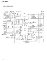
Page 60: ...60 CDX FM657 7 3 BLOCK DIAGRAM A C D E B ...
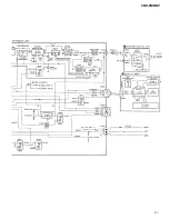
Page 61: ...61 CDX FM657 F G ...


