background image

- 1 -

Introduction

WARNING
To prevent fire or shock hazard, do not expose
the unit to rain or moisture.

INFORMATION

This equipment generates and uses  radio frequency
energy and if not installed and used properly; that is,
in  strict  accordance  with  the  manufacturer’s
instructions,  may  cause  interference  to radio  and
television reception.  It  has  been  type  tested  and
found  to  comply with  the limitations for  a  Class  B
computing  device  in  accordance  with  the
specifications in  Subpart  J of  Part  15  of the  FCC
Rules,  which  are  designed to  provide  reasonable
protection  against such  interference  in a  residential
installation. However,  there  is no  guarantee  that
interference will not occur in a particular installation.
If this equipment does cause interference to radio or
television  reception,  which  can  be  determined  by
turning  the  equipment  off and  on,  the  user  is
encouraged to try to correct the interference by one
or more of the following measures:

- Reorient or relocate the receiving antenna.
- Increase the separation between the equipment and

receiver.

- Connect  the  equipment to  an  outlet  of  a  circuit

different  from  that  to   which  the  receiver  is
connected.

- Consult  the  dealer  or  on  experienced radio/TV

technicion for help.

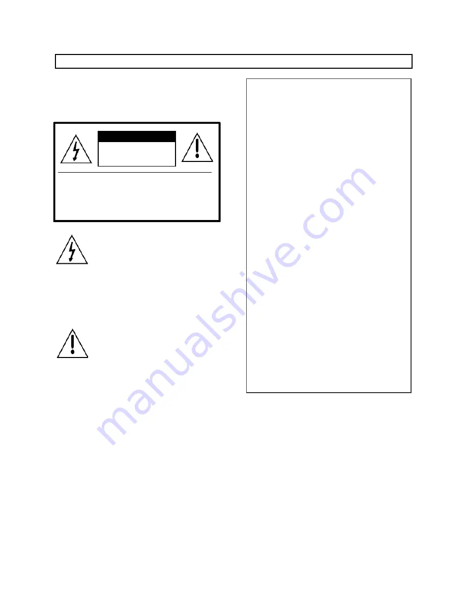
This symbol  is  intended to  alert  the
user  to  the  presence  of  uninsulated

“dangerous voltage”

within  the

product’s  enclosure  that  may  be  of
sufficient  magnitude  to  constitute  a
risk of electric shock to persons.

This  symbol  is  intended to  alert  the
user  to  the  presence  of  important
operating  and  maintenance
(servicing)  instructions  in  the
literature accompanying the unit.

CAUTION : TO REDUCE THE RISK OF ELECTRIC SHOCK, DO

NOT REMOVE COVER (OR BACK). NO USER-SERVICEABLE
PARTS INSIDE. REFER SERVICING TO QUALIFIED SERVICE
PERSONNEL.

CAUTION

RISK OF ELECTRIC SHOCK

DO NOT OPEN

TO  PREVENT  ELECTRIC  SHOCK,  DO  NOT  USE
THIS  POLARIZED  AC  PLUG  WITH  AN
EXTENSION  CORD,  RECEPTACLE  OR  OTHER
OUTLET,  UNLESS  THE  BLADES  CAN  BE  FULLY
INSERTED TO PREVENT BLADE EXPOSURE.

Summary of Contents for CDS-481L

Page 1: ...orrect the interference by one or more of the following measures Reorient or relocate the receiving antenna Increase the separation between the equipment and receiver Connect the equipment to an outlet of a circuit different from that to which the receiver is connected Consult the dealer or on experienced radio TV technicion for help This symbol is intended to alert the user to the presence of uni...

Page 2: ...ufacturer 9 A product and cart combination should be moved with care Quick stops excessive force and uneven surfaces may cause the product and cart combination to overturn 10 Ventilation Slots and openings in the cabinet are provided for ventilation and to ensure reliable operation of the product They protect it from overheating and these openings must not be blocked or covered The openings should...

Page 3: ...ction of this product during a lightning storm or when it is left unattended and unused for long periods of time unplug it from the wall outlet and disconnect the antenna or cable system This will prevent damage to the product due to lightning and power line surges 17 Power Lines An outside antenna system should not be located in the vicinity of overhead power lines or other electric light or powe...

Page 4: ...arts are required be sure the service technician has used replacement parts specified by the manufacturer or have the same characteristics as the original part Unauthorized substitutions may result in fire electric shock or other hazards 23 Safety Check Upon completion of any service or repairs to this product ask the service technician to perform safety checks to determine that the product is in ...

Page 5: ...gement System 16 9 Announcement 17 10 Call Block 18 11 Away Mode Setting and Security Mode Extension from the Guardhouse 19 12 Emergencies within Households 22 13 Delivery 24 14 Confirming Household Conditions 25 15 Adjusting Time 30 16 Advanced Feature Please use only after understanding its handling to the full 16 1 Registering Household Numbers 31 16 2 Registering Household Vehicles Parking Man...

Page 6: ...rted Using 8 wire common wiring method between the Main Entrance interphone and the Guardhouse interphone this system supports 3 communication circuits and each communication circuit is a Balance Type that supports 2 wires Using 18 wire common wiring method between the Guardhouse interphone and the Guardhouse interphone this system supports 8 communication circuits and each communication circuit i...

Page 7: ...justment 10 Key Pad 11 Call Block Button 12 Confirmation Button 13 Change Location Buttons 14 Open 15 Emergency Page 16 Speed Dial Buttons 17 P A Button 18 Call Connection Button 19 Speakerphone 20 Call Button 21 Parking Management System 22 Emergency Lamp 23 Away Lamp 24 Call Lamp 25 Guardhouse Indicator Section 26 Household Indicator Section 27 Building Button 28 Outside Line Lamp 29 Internal Li...

Page 8: ...use Remote Control Button Lam Used to verify and adjust various information of the Household Videophone Button Lamp Used to confirm or make changes to entered data Extension Button Lamp Used to assign Multi Sub numbers to the Household Videophone and in various other extension processes Redial Button Lamp Pages the last number paged Emergency Page Lamp Pages to connect to a Household with an emerg...

Page 9: ...atus of each outside line 1 to 16 Internal Line Indicator LED Indicates the status of each internal line 1 to 3 Confirmation Button Used when verifying a Household using Vehicle Number Vehicle Button Used to page a Household using Vehicle Number Two vehicles can be registered per household Emergency Indicator Blinks when an Emergency Page has been made Away Indicator Blinks when an Emergency Page ...

Page 10: ... while the Outside Line 1 button has been pressed The last Household connected to the Household on line is displayed on the LCD Inform the Household of its last connection 4 1 1 Request from the Household to Confirm the Last Household it has Connected to Pickup the Receiver to answer LCD Call 0101 0101 Pickup the Receiver to answer ex From Building 101 Unit 101 Connected to the Household Press the...

Page 11: ...ng button The number indicated on the LCD and the Guardhouse Indicator Section moves to the Building location Enter the Household Number using the Key Pad To page another Guardhouse enter the Guardhouse Interphone s Serial Number Press the Call button Ringing tone will sound Await a reply If a busy signal is heard hang up and page again after a few minutes Building button Call button Paging Tone w...

Page 12: ...d to enter in the Household Building Number to connect to and press the Building button Hang up Building button After Entering the Household Building Number Use the Key Pad to enter in the Household Number to connect to and press the Page button Ringing tone lit up Call Connect lamp and Exchange OK indicated on the LCD Page button LCD Exchange OK Beep Beep If wrong Building Number or Household Num...

Page 13: ... the initial call to connect with the second Household Note If the Household indicated on the Household Indicator Section is not selected within 30 seconds that Household will no longer be indicated on the top portion of that section and be replaced by the next Household in line When the Guardhouse is on a call with Unit 101 from Building 101 Ex Being paged by Unit 303 from Building 101 After Endi...

Page 14: ...ardhouse has been paged from the Main Entrance Main Entrance Number indicated on the LCD and the Guardhouse Indicator Section Pressing the Door Release button while connected to an entrance will open it LCD Call 0101 9901 A Paging Signal will Sound ex 101동 1번째 공동현관에서 호출이 올 경우 The Main Entrance will Open Pickup the receiver to answer ...

Page 15: ...of the entrance to connect to Press the Page button Await for a reply Ex To connect to the first Main Entrance of Building 101 Page button A Paging Signal will Sound Connecting to the Main Entrance The Main Entrance will Open Pressing the Door Release button while connected to an entrance will open it ...

Page 16: ...nagement System To page a houshold using the above vehicle number Pickup the receiver Press the Vehicle Button Enter 32 Press the Building button Enter 2580 Press the Page button Wait for a reply Await a reply Ex Gyeonggi 32 Ga 2580 Vehicle Number Region Number 1 to 2 digits Enter the Region Number 1 to 2 digits Enter the Vehicle Number 4 digits LCD Car Use the Key Pad to enter in the vehicle s re...

Page 17: ...f the Guardhouse interphone 00 All Announcement is heard through all installed Guardhouse interphones 01 Group 1 only Announcement is heard through Guardhouse interphones designated under Group 1 only If the Guardhouse interphone is on a call the announcement will not be made through that interphone On the LCD of the Guardhouse interphone where the announcement is made from numbers of announcement...

Page 18: ...l light up To disable press the Call Block button once more Pressing the Speakerphone button or picking up the receiver will also disable All calls are forwarded to the designated Guardhouse Method 1 Press the Call Block button again Method 2 Pickup the receiver Method 3 Press the Speakerphone button Note To configure it so that this feature continues to be active when the Guardhouse interphone ha...

Page 19: ...Guard 11 Away Mode Setting and Security Mode Extension from the Guardhouse 11 1 Setting the Household in Away Mode from the Guardhouse Press the Away button Away LED lights up Speakerphone LED lights up Enter the Building Number of the Household to have set in Away Mode then the Building button and the Household Number then the Call button The following message will appear on the LCD If a door ins...

Page 20: ...rdhouse Pickup the receiver or press the Speakerphone button Enter the Building and Household Number and press the Call button If the residents are away oUt OUT will be displayed Put down the receiver to end After Confirming the Away Status Blinking LED Currently Away Or Building button Call button ...

Page 21: ... the Away button When the Security Guard has been delayed the following will appear on the LCD Press the Speakerphone button to end Household Security Guard Activation has been delayed For 10 minutes from the moment of ordering Guard Activation Delay no alarm will sound even if the Household door is opened Building button LCD Sensor Chk Wait ...

Page 22: ...n will sound and Building and Household numbers will blink on the Household Indicator Section This state will continue until an emergency page has been made to that Household from the Guardhouse If the Household 1 is in Away Mode the Away lamp LED will also blink 12 2 Emergency Page Pickup the receiver or press the Speakerphone button then press the Emergency Page button The highest ranking Househ...

Page 23: ...ated on the Guardhouse Indicator Section If the Household cannot sound alarms each of the following situations is indicated Place the receiver down to end Electronic Gun Emergency Fire Truck Fire Ambulance Gas Leak Police Siren Burglar Intrusion When the blinking stops the page is made Alarm corresponding to the emergency is sounded ...

Page 24: ... that has made the Delivery Page Press the Speakerphone button Press the Delivery button Press the Speakerphone button to end The Household will call Building button Power lamp on the Household Videophone blinks Enter the Building Number press the Building button and enter the Household Number ...

Page 25: ...Number and press the Extension button If the Page button is pressed instead of the Extension button the Master is selected Enter the Multi Sub Number and press the Page button SUB Numbers range from 0 to 9 The following are indicated on 7 Segment When Master is Selected LCD Rmot Building button Call button A Household s Current Status B Household Number C Household Sensor Status D Household s Burg...

Page 26: ...tion Fire Activation of Fire Sensors within the Household Gas Activation of Gas Detectors within the Household Burglar Detection of Intrusion Out Door House Residences Away Busy The Household is currently on a call B Household Number Indicates the Household currently under review Press the Household Select button 1 to view other Households ...

Page 27: ...rs within the Household activated 1 Security 1 Security 1 activated 1 Security 2 Security 2 activated 1 Security 3 Security 3 activated 1 Security 4 Security 4 activated 1 Emergency Fire Gas Security 1 Security 2 Security 3 Security 4 Security 1 Security 2 Security 3 Security 4 D Household s Burglary Status Away Status Indicated when residences are away Indicates active burglary sensors within the...

Page 28: ...one is connected to a Household only its Master is checked Press the Remote Control button Enter the Building Number press the Building button then enter in the Household Number on the lowest floor of that building Press the Extension button Press the Confirmation button LCD Rmot Building button Ex When Unit 101 Building 101 has been entered LCD Auto Scan Test ...

Page 29: ...utomatically checked Error will be indicated on the Guardhouse Indicator Section if an error is detected and its details are indicated on the Household Indicator Section Automatic inspection is paused Press the Call button Press the Call button again to skip to the next Household LCD End Zone Select Call button Call button ...

Page 30: ...Minute W Day of the Week Days of the Week 0 Sun 1 Mon 2 Tue 3 Wed 4 Thu 5 Fri 6 Sat Enter hours based on the 24 hour clock Press the Enter button Ex To Set as Monday October 11th 1999 9 30AM Time Adjustment Button 99년 10월 11일 09시 30분 1 Enter Button Year Month Day Time Minute Day of the Week Enter hours based on the 24 hour clock LCD YY MM DD HH MM W YY MM DD HH MM W ...

Page 31: ...he Guard button from the Household Pickup the receiver and press the Remote Control button from the Guardhouse Enter the Building Number and press the Building button Enter the Household Number and press the Extension button Building button If the Page button is pressed instead of the Extension button the Master is registered 16 Advanced Feature Please use only after understanding its handling to ...

Page 32: ... Numbers are from 1 to 9 Maximum 10 videophones can be installed in a household and their serial numbers must not overlap Register Sub Serial Numbers in the order from 1 to 9 A Master must exist among numerous videophones If only one videophone exists that unit shall be registered as the Master Enter the Multi Sub Number and press the Call button When the Household is the Master Call button ...

Page 33: ...n Vehicle Number Press the Speakerphone button then the Remote Control button Just the Remote Control button may be pressed Enter the Building Number and the Household Number then page Already registered data are shown as indicated below Household Number Ex Unit 102 Building 101 Household Vehicle 1 Ex Gyeonggi 32Ga2580 Household Vehicle 2 Ex Gyonggi 32Nuh4381 Not Used Not Used Building button Call...

Page 34: ...icator Section displays whether data can be modified or not Enter the vehicle s region and assigned numbers button distinguishes the two Use the buttons to undo wrong entries Press the Call Connect button Press the Remote Control button The blinking light stops Ex Gyeonggi 32 Ga 2580 Assigned Number Region Number 1 or 2 digits ...

Page 35: ...gion Number 1 or 2 digits Assigned Number 4 digits Mister our vehicle number is Gyeonggi 32 Ga 2580 Building button 16 2 2 Registration by the Household through the Guardhouse Only possible when the Household pages the Guardhouse Pickup the receiver and press the Remote Control button while staying connected to the Household Ex Gyeonggi 32 Ga 2580 Assigned Number Region Number 1 or 2 digits ...

Page 36: ... and Entry 2 for the entered vehicle number to store Put down the receiver to end 16 3 Checking Household Numbers using Vehicle Numbers Press the Speakerphone button Press the Confirmation button of the Parking Management System car indicated on the LCD LCD Car ...

Page 37: ...y Release the Main Entrance Pickup the receiver Enter the Building Number of the Entrance then press the Building button Enter the Entrance Interphone s Serial Number then press the Call button LCD Car 32 2580 Building button Call button Building button Call button Ex Vehicle Number of Unit 101 Building 102 being Gyeonggi 32 Ga 2580 Vehicle number is displayed on the LCD and the Household Number i...

Page 38: ... 38 Press the Door Release button to open the entrance Put down the receiver to end ...

Page 39: ... Enter the Building Number of the entrance the press the Building button Enter the Entrance Interphone s Serial Number then press the Open button Entrance opens The Door Release lamp will stay lit up When a Main Entrance is opened the Door Release of all Guardhouse Interphones connected to that entrance remains lit Building button ...

Page 40: ...cess indicated on the LCD Press the Confirmation button Open Lobby XX indicated on the LCD XX is the number of opened entrances The number of opened entrance interphones is indicated on the Household Indicator Section LCD Lobby process LCD Open Lobby 1 ex One opened entrance ...

Page 41: ...using the Household Selection button Selected Entrance Interphone Number moves to the Guardhouse Indicator Section Press the Open button Closes the selected entrance Use buttons to find the entrance to close select the entrance interphone using the Household Selection button Using Household Select buttons choose the Main Entrance Interphone ...

Page 42: ...usehold 4 101 9904 The fourth open entrance interphone To close the second open entrance 101 9902 press Open and the Confirmation button press the Household Selection button 2 101 9902 moves to the Guardhouse Indicator Section then Open button Guardhouse Indicator Section The first open entrance interphone The second open entrance interphone The third open entrance interphone The fourth open entra...

Page 43: ...select the desired program Refer to Guardhouse Interphone Program Number and Description of Table 1 The following are displayed on the LCD For entry numbers please refer to Guardhouse Interphone Program Number and Description of Table 1 New Data Current Data Program Number Use the Key Pad to enter in the new data then press the Enter button After Entering the Program Number LCD Password LCD Progra...

Page 44: ...the Key Pad to enter in 8888 then press the Enter button Entry lamp will turn on and Prog XXXX Wait will display on the LCD Do not power off until the Entry lamp turns off The entries may be erased Press the Speakerphone button to end Wait Do not modify Programs 00 and 01 except for during installation Improper modifications will disable the calling feature LCD Pr31 0000 LCD Prog 0000 Wait ...

Page 45: ...n charge of are Buildings 101 and 102 Press the Confirmation button Use buttons to select Pr 05 Enter in 101 Building No then press the Enter button Use buttons to select Pr 06 Enter in 101 Building No then press the Enter button Enter in 9999 then press the Enter button LCD Pr05 0000 LCD Pr06 0000 After Entering 101 After Entering 102 ...

Page 46: ...rage Prog XXXX Wait will display on the LCD Wait LCD Pr31 0000 LCD Prog 0000 Wait Do not power down until the entry lamp has turned off From now Buildings 101 and 102 must not be overlapped as the SUB buildings of any other Guardhouse interphones Important ...

Page 47: ...he Guardhouse Interphone Pr 10 No 6 Sub Building No Assigned to the Guardhouse Interphone Pr 11 No 7 Sub Building No Assigned to the Guardhouse Interphone Pr 12 No 8 Sub Building No Assigned to the Guardhouse Interphone Pr 13 No 9 Sub Building No Assigned to the Guardhouse Interphone Pr 14 No 10 Sub Building No Assigned to the Guardhouse Interphone Pr 15 No 11 Sub Building No Assigned to the Guard...

Page 48: ... Guardhouse Interphone Call 9 to 16 Communication path can only be expanded if CDS 481S has been installed Pr 02 Call time is set by default as 3 minutes Values 0001 to 0007 are additional minutes to the standard 3 minutes Values other than 0001 to 0007 are not accepted Modified data is stored in all installed Guardhouse and Household Interphones Pr 03 Connection is only available when calls are s...

Page 49: ...all 6 TIV 0 65mm 2C Non Polar 13 14 Call 7 TIV 0 65mm 2C Non Polar 15 16 Call 8 TIV 0 65mm 2C Non Polar 17 Data TIV 0 65mm Polar 18 GND TIV 0 65mm Polar 1 2 Call 1 TIV 0 65mm 2C Non Polar 3 4 Call 2 TIV 0 65mm 2C Non Polar 5 6 Call 3 TIV 0 65mm 2C Non Polar 7 8 Call 4 TIV 0 65mm 2C Non Polar 9 10 Call 5 TIV 0 65mm 2C Non Polar 11 12 Call 6 TIV 0 65mm 2C Non Polar 13 14 Call 7 TIV 0 65mm 2C Non Pol...

Page 50: ...Interphone DRC 481L Security DC 12V used Designed to be used by connecting to the lead switch When not in use please connect two wires When the Main Entrance is opened by force the Guardhouse and the computer are notified ...

Page 51: ... 51 3 Household Videophone CH 481SL 4 Household Videophone APV 481FT ...

Page 52: ... 52 5 Household Videophone CAV 60FSD 6 Household Videophone CAV 60FD ...

Page 53: ... 53 7 Household Videophone CAV 561D ...

Page 54: ... 54 8 Household Videophone CAV 482S ...

Page 55: ... 55 9 TV Phone Interface Adaptor ADT 481 10 Security Interface Adaptor ADT 482 ...

Page 56: ... 56 11 System Map ...

Page 57: ... 57 12 Wiring Method for Communications with the Guardhouse ...

Page 58: ...Or Y CALL GND VD IN VD OUT 2 Household Videophone Bk Br R Or Y 3 If the Guardhouse Interphone CDS 481L has been installed Number 7 Data and 8 GND connected to it must be connected to the Household Interphone 4 Use coaxial cables 3C2V or 5C2V for Video Out CALL GND VD IN VD OUT ...

Page 59: ... 59 14 Wiring ADT 481 and CKV 60T 15 Wiring ADT 482 and CAV 482S ...

Page 60: ... Common 2 When registering the Multi Sub number ADT 481 will not be recognized as the Master and should be installed last as shown above 3 Various types of sensors should be connected to the Master and sensors of the remaining Subs should be connected with the wire and the sensor line if the two lines are not connected the Away mode will not function ...

Page 61: ... 61 17 CCTV and Sensor Wiring NOTE 1 Monitor 1 To view only when being used by the Main Entrance Interphone DRC 481L 2 Monitor 2 Continuous surveillance of the Main Entrance ...

Page 62: ... 62 18 Wiring DRC 481L and CDS 481PC NOTE To be wired when the Finger Print Recognition device has been installed and the wiring must use STP 4P ...

Page 63: ... 63 19 Wiring CDS 481PC and Multi Port ...

Page 64: ... 8 wire common Outside call extension 16 wire common optional Rated Voltage AC 110 220V 60Hz FREE VOLTAGE Power Consumption Max 10W Standby 4 5W Communication Method Synchronous Communication Method Communication Distance 1Km Using ф0 65mm Cable Ambient Temperature 10 50 Dimensions 328 W 230 H 97 D mm CDS 481L ...

Page 65: ...03 07 00 513 11 Sangdaewon dong Jungwon gu Seongnam si Gyeonggi do Korea Int l Businne Dept Tel 82 31 7393 540 550 Fax 82 31 745 2133 Web site www commax co kr Printed In Korea ...

Page 66: ...Use And Care Guide Model No CDS 481L GUARDHOUSE INTERPHONE BY COMMAX Before operating the unit please read this manual thoroughly and retain it for future reference ...

Reviews: