background image

English

4

En

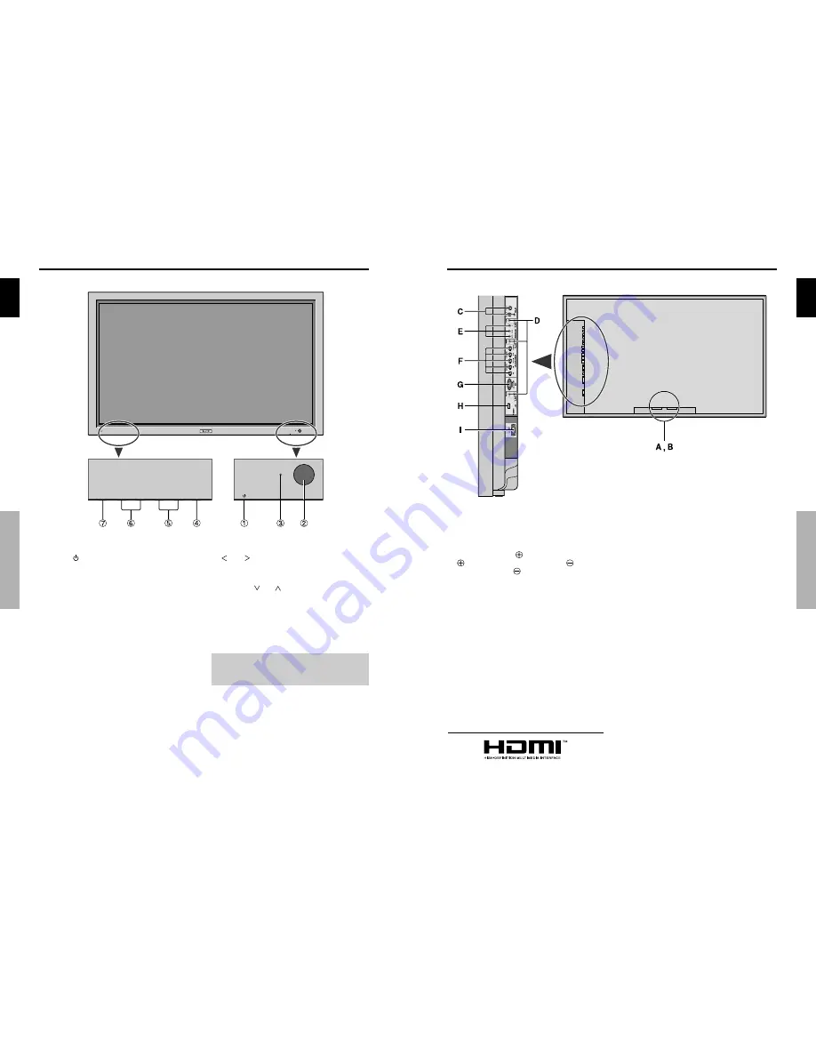
q

Power ( 

 )

Turns the monitor’s power on and off.

w

Remote sensor window

Receives the signals from the remote control.

e

STANDBY/ON indicator

When the power is on ............................. Lights green.
When the power is in the standby mode ... Lights red.

r

INPUT/EXIT

Switches the input.
The available inputs depend on the setting of “BNC
INPUT” and “RGB SELECT”.
Functions  as  the  EXIT  buttons  in  the  On-Screen
Display (OSD) mode.

Front View

t

  and  

Functions as the CURSOR (


) buttons in the On-

Screen Display (OSD) mode.

y

VOLUME 

 and 

Adjusts the volume. Functions as the CURSOR (

/

) buttons in the On-Screen Display (OSD) mode.

u

MENU/SET

Sets the On-Screen Display (OSD) mode and displays
the main menu.

WARNING

The Power on/off switch does not disconnect the plasma
display completely from the supply mains.

Part Names and Function

Part Names and Function

English

5

En

A

AC IN

Connect the included power cord here.

B

EXT SPEAKER L and R

Connect speakers (optional) here. Maintain the correct
polarity. Connect the 

 (positive) speaker wire to the

  EXT  SPEAKER  terminal  and  the 

  (negative)

speaker wire to the 

 EXT SPEAKER terminal on

both LEFT and RIGHT channels.
Please refer to your speaker’s owner’s manual.

C

VIDEO1, 2, 3 (BNC, RCA, S-Video)

Connect VCR’s, DVD’s or Video Cameras, etc. here.

D

AUDIO1, AUDIO2, AUDIO3

These are audio input terminals.
The input is selectable. Set which video image to allot
them from the SOUND menu screen.

E

COMPONENT 1

Connect DVD’s, High Definition or Laser Discs, etc.
here.

F

PC2/ COMPONENT2

PC2:

You  can  connect  an  analog  RGB
signal and the syncronization signal.

COMPONENT2: You  can  connect  DVDs,  High

Definition sources, Laser Discs, etc.
here.
This input can be set for use with an
RGB or component source (see page
19).

G

PC1 (D-Sub)

Connect an analog RGB signal from a computer, etc.
here.

H

HDMI

Connect a digital signal from a source with a HDMI
output.
See page 30 for the details of Supported Signals.

I

RS-232C (D-Sub)
Never  connect  any  component  to  this  connector
without  first  consulting  your  Pioneer  installation
technician.

This  connector  is  used  for  plasma  display  setup
adjustments.

Rear View/ Terminal Board

Part Names and Function

HDMI, the HDMI logo and High-Definition Multimedia Interface are 
trademarks or registered trademarks of HDMI Licensing LLC.

Summary of Contents for 1410HD

Page 1: ...t useful in the future Note for Dealers After installation be sure to deliver this manual to the customer and explain to the customer how to handle the product Notes on Installation Work This product is marketed assuming that it is installed by qualified personnel with enough skill and competence Always have an installation specialist or your dealer install and set up the product PIONEER cannot as...

Page 2: ...facturer is not liable for any bodily harm or damage caused if unqualified persons attempt service or open the back cover Refer all service to authorized Service Centers English Important Information 3 En ii En To avoid damage and prolong operating life 1 Use only with 120V 60Hz AC power supply Continued operation at line voltages greater than 120 Volts AC will shorten the life of the unit and mig...

Page 3: ...ipod bracket ortablespecifiedbythemanufacturer orsold withtheapparatus Whenacartisused use cautionwhenmovingthecart apparatus combinationtoavoidinjuryfromtip over 13 Unplugthisapparatusduringlightningstormsorwhen unusedforlongperiodsoftime 14 Referallservicingtoqualifiedservicepersonnel Servicingisrequiredwhentheapparatushasbeen damagedinanyway suchaspower supplycordorplug isdamaged liquidhasbeens...

Page 4: ...e menus 12 Menu Tree 13 Picture Settings Menu 15 Storing picture settings 15 Adjusting the picture 15 Reducing noise in the picture 15 Setting the color temperature 16 Adjusting the color to the desired level 16 Changing the Gamma Curve 16 Making the Low Tone adjustments 16 Adjusting the pedestal level black level 17 Adjusting the colors 17 Setting the picture to suit the movie 17 Setting the pict...

Page 5: ...space between surrounding objects as shown on the diagram below when installing Installation When installing or carrying use the handles attached to the upper back of the display Installation English 3 En cables clamp mounting hole How to use the remote control Battery Installation and Replacement Insert the 2 AAA batteries making sure to set them in with the proper polarity 1 Press and open the c...

Page 6: ...erminal and the negative speaker wire to the EXT SPEAKER terminal on both LEFT and RIGHT channels Please refer to your speaker s owner s manual C VIDEO1 2 3 BNC RCA S Video Connect VCR s DVD s or Video Cameras etc here D AUDIO1 AUDIO2 AUDIO3 These are audio input terminals The input is selectable Set which video image to allot them from the SOUND menu screen E COMPONENT 1 Connect DVD s High Defini...

Page 7: ...and OFF 1 Plug the power cord into an active AC power outlet 2 Press the Power button on the unit The monitor s STANDBY ON indicator turns red and the standby mode is set 3 Press the POWER ON button on the remote control to turn on the unit The monitor s STANDBY ON indicator will light up green when the unit is on 4 Press the POWER STANDBY button on the remote control or the Power button on the un...

Page 8: ...black bands appear on the top and bottom in the full size screen selectthe2 35 1sizescreentoavoidphosphorburn in 14 9 size screen The image is displayed at a 14 9 aspect ratio This feature is available when the input signal is video component 480I 480P or RGB 525P signal from a scan converter Note Do not allow the displayed in 4 3 mode for an extended period This can cause a phosphor burn in Infor...

Page 9: ...C A B VIDEO1 PC2 BNC B A Side by Side2 R Side by Side1 Side by Side2 L Side by Side4 R Side by Side3 Side by Side4 L button button button button button button button button button button button button button button English 11 En SPLIT SCREEN Operations Operations in the Picture in picture mode To move the position of the sub screen press the cursor or button To change the size of the sub screen pr...

Page 10: ... PICTURE PICTURE MEMORY OFF MEMORY1 6 YES 15 CONTRAST 0 52 72 YES 15 BRIGHTNESS 0 32 64 YES 15 SHARPNESS 0 16 32 YES 15 COLOR 0 32 64 YES 15 TINT R G 0 32 64 YES 15 DNR OFF LOW MID HIGH YES 15 COLOR TEMP LOW MIDDLE LOW MIDDLE HIGH YES 16 WHITE BALANCE R HIGH 0 40 70 YES 16 G HIGH 0 40 70 YES 16 B HIGH 0 40 70 YES 16 R LOW 0 40 70 YES 16 G LOW 0 40 70 YES 16 B LOW 0 40 70 YES 16 RESET OFF ON YES 16...

Page 11: ...y place MEMORY1 to MEMORY6 then use the and buttons to select RESET and finally press the MENU SET button The memory is cleared and is displayed in the INPUT SIGNAL and NOTE columns Inputting notes Use the and buttons to select NOTE then press the MENU SET button Input the note Use the and button to select the character Use the and buttons to move the cursor Use the EXIT button to delete the chara...

Page 12: ...density for red green blue yellow magenta and cyan You can accentuate the green color of trees the blue of the sky etc Example Adjusting the color management for blue On PICTURE menu select COLOR MGT then press the MENU SET button The COLOR MGT screen appears On BLUE of COLOR MGT adjust the color management SEL ADJ EXIT RETURN COLOR MGT RED GREEN BLUE YELLOW MAGENTA CYAN RESET OFF R G M C Y B B R ...

Page 13: ...al position of the image V SIZE Adjusts the vertical size of the image Except for WIDE mode H SIZE Adjusts the horizontal size of the image Except for WIDE mode PHASE Adjusts for flickering CLOCK Adjusts for striped patterns on the image The CLOCK and PHASE features are available only when the Auto Picture is off The AUTO PICTURE PHASE and CLOCK are available only for RGB signals But these feature...

Page 14: ...HD SELECT RGB SELECT HDMI SET UP COLOR SYSTEM BACK GROUND SIDE MASK S1 S2 DISPLAY OSD OSD ADJUST ALL RESET ENGLISH COMPONENT RGB 1080I AUTO COLOR1 AUTO BLACK 3 OFF ON TOP LEFT OFF Information BACK GROUND Settings BLACK Sets the background color to black GRAY Sets the background color to gray Setting this makes it easier to see that there is no signal English OSD On Screen Display Controls 21 En Se...

Page 15: ... when the input signal is lost Loss of the input signal means a condition in which the video signal and the sync signal are not present Under conditions in which the sub screen has disappeared the ZOOM NAV and PICTURE FREEZE functions will not work The SCREEN SIZE button will not function either SUB P DETECT settings AUTO The black frame disappears 3 seconds after the input signal is lost OFF Turn...

Page 16: ...PER of LONG LIFE menu select ON SEL ADJ EXIT RETURN LONG LIFE ABL ORBITER INVERSE WHITE SCREEN WIPER SOFT FOCUS OSD ORBITER OSD CONTRAST 100 OFF OFF ON OFF ON LOW Information SCREEN WIPER ON The white vertical bar appears OFF Screen wiper mode does not function SOFT FOCUS Reduces edges and softens the image Example Setting SOFT FOCUS to LEVEL2 On SOFT FOCUS of LONG LIFE menu select LEVEL2 SEL ADJ ...

Page 17: ...ES 2 YES YES YES YES YES YES YES YES YES YES YES YES YES YES 3 YES 3 YES 3 YES 3 YES 3 YES YES 4 YES 4 YES 4 YES 4 YES YES YES YES YES YES YES YES 3 YES YES 4 YES 4 YES 4 YES YES YES 4 YES 3 YES 4 YES 7 D BY D YES YES YES FULL 16 9 YES YES YES YES YES YES YES YES YES YES YES YES YES YES YES YES YES YES YES YES YES YES YES YES YES YES YES YES 3 YES 3 YES YES YES YES YES YES YES YES YES YES YES YES ...

Page 18: ...control and adjust properly Set to the proper resolution Check the input signal Promptly switch off the power of the main unit and wait until the internal temperature drops See 1 Prompty switch off the power of the main unit See 2 If the picture quality is poor or there is some other problem check the adjustments operations etc before requesting service Maybe the sound from the cooling fans used t...

Page 19: ...Converter NTSC PAL 480I 525I 1035I 1080I 2 3 pull down Converter NTSC 480I 525I 1035I 1080I 60Hz 2 2 pull down Converter PAL NTSC 480I 525I Digital Zoom Function 100 900 Selectable Self Diagnosis Image Burn reduction tools ABL INVERSE WHITE ORBITER SCREEN WIPER Color Temperature select high middle middle low low user has 4 memories Auto Picture Input Skip Color MGT Low Tone 3 mode Gamma Correction...

Reviews: