6
Programming the Hunter-Pro series with an LED keypad
3.2
Setting a discrete parameter’s values
The next example demonstrates how setting a set of discrete parameters (e.g. CMS #1
communication parameters) is performed: the LEDs that illuminate in the upper line
mark where the ‘cursor’ is; the LEDs in the bottom line mark the value, which can be
one of two, in a way that resembles to the LCD keypad display: illuminating LEDs
represent ‘+’ or ‘Enabled’; turned off LEDs represent ‘-’ or ‘Disabled’.
The full description of each and every parameter is detailed in the
Hunter-Pro series installation guide.
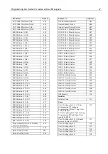
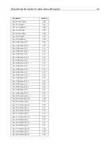
All the parameters with their addresses are listed in chapter 3
When programming discrete parameters, reading the upper line is from left to right
and so, in the next screen, the red illuminating LED, i.e. the ‘cursor’, is on the second
parameter. Advance the ‘cursor’ with NEXT & BACK buttons.
In the figure below, the values demonstrated are +---+-++ where ‘+’ is enabled and ‘-‘
is disabled.
3.3
Example: setting ‘Mains fault delay time’
To begin with, look in the parameters addresses table in chapter
4. ‘Mains fault delay
time’ timer has the address of 339. Assume we want to set its value (i.e. time) to 35
minutes (the default value is 15). The programming flow goes like this:
1.
Enter the installer code. No LED should flash but the red Armed one, to indicate
that the keypad is now in programming mode.


