background image


4


Programming the Hunter-Pro series with an LED keypad


Figure 2.


Setting an address 

RXN-416

1

2

3

4

5

6

7

8

9

10

11

12

13

14

15

16

+

-

-

-

+

-

+

+

When inserting discrete data the behavior of the keypad is the same as the LCD
one: the top line shows where the ‘cursor’ is (looking from left to right) and the
bottom shows the toggle status of the parameter: illuminating LED represents ‘+’
which means enabled; off LED represents ‘-‘ which means disabled.
If the Hunter-Pro menu contains more than 8 parameters, the first 8 are part of the
first byte and the second 8 are part of the second byte (applies to the address table
in chapter 3)

Top line illuminating LED:
Location of the ‘cursor’

One byte


Figure 3.


Reading discrete data 

The LED keypad programming flow resembles the LCD keypad flow to some extent.   

2.1


The LEDs 

1.


When the system is in programming mode the Red Armed LED indicates by flashing 
fast. The Green fault LED indicates whether the parameter’s address is being set or 
its value: 

Green LED

Red LED

Mode

Flashes fast

Off

Programming: inserting an address

Flashes fast

Flashes slowly

Programming: Inserting a value (parameter)

2.


When the system is in address setting mode, the address value is determined by 
the combination of the illuminating LEDs in both the 2 lines. 

3.


When the system is in parameter setting mode, the upper illuminating LEDs mark 
the position (as a digit or bit) of the ‘cursor’ (as in the LCD keypad), and the bottom 
line mark the value of this parameter (as a digit or bit).  

4.


All numbers, e.g. telephone numbers, timings, etc., are displayed in hexadecimal 
(base-16) system. A conversion table is in the next sub-section.  

Summary of Contents for Hunter-Pro RXN-416

Page 1: ...RXN 416 LED Keypad Installer Programming Guide For the Hunter Pro Series PIMA Electronic Systems Ltd www pima alarms com P N 4410289 A1 ZA en March 2009 ...

Page 2: ...id 57 Warning The user should follow the installation and operation instructions and among other things test the Product and the whole system at least once a week For various reasons including but not limited to changes in environment Warning The user should follow the installation and operation instructions and among other things test the Product and the whole system at least once a week For vari...

Page 3: ...e numbers 2 Discrete or toggle e g zone characteristics partitions etc these 2 state parameters represent or Both types are displayed by the keypad LEDs where an illuminating LED stands for 1 or enabled in discrete data and a turned off LED stands for 0 or disabled in discrete data In discrete programming mode the pound key is used for toggling the parameters value between and i e enabled and disa...

Page 4: ... LED keypad programming flow resembles the LCD keypad flow to some extent 2 1 The LEDs 1 When the system is in programming mode the Red Armed LED indicates by flashing fast The Green fault LED indicates whether the parameter s address is being set or its value Green LED Red LED Mode Flashes fast Off Programming inserting an address Flashes fast Flashes slowly Programming Inserting a value paramete...

Page 5: ...N HEX BIN HEX BIN 0 0000 4 0100 8 1000 C 1100 1 0001 5 0101 9 1001 D 1101 2 0010 6 0110 A 1010 E 1110 3 0011 7 0111 B 1011 F 1111 3 PROGRAMMING EXAMPLES 3 1 Displaying a number 1 Displaying a number that starts with 3 2 Displaying 6 as the 3rd digit of a number Account numbers are made of 4 digits therefor any account number that has less than 4 digits must be preceded with zeros For example accou...

Page 6: ...ation guide All the parameters with their addresses are listed in chapter 3 When programming discrete parameters reading the upper line is from left to right and so in the next screen the red illuminating LED i e the cursor is on the second parameter Advance the cursor with NEXT BACK buttons In the figure below the values demonstrated are where is enabled and is disabled 3 3 Example setting Mains ...

Page 7: ... displayed the hex digit of the upper line is 0001 which is decimal 1 therefor the cursor is on the first digit of the number value The bottom line displays 2 as the value digit 4 Press 3 the first digit of the new value 35 Just like in the LCD keypad when entering the first digit of a number value the stored number is erased and the cursor automatically advances to the second space which is now b...

Page 8: ... LED keypad are fully displayed even if only part of the field is in use In this example the requested value is a two digit number 35 but the Entry delay time field contains 3 digits and so the 3rd digit which is blank is displayed too 6 Press ENTR to save the new value and return to address programming mode 1 2 3 4 5 6 7 8 9 10 11 12 13 14 15 16 RXN 416 Armed Fault Programming mode Red Armed LED ...

Page 9: ...address table on chapter 4 Zone 3 characteristics menu byte 1 has the address of 252 Enter the installer code and press 252 The keypad will enter into programming mode and display the address 2 Press ENTR The keypad displays zone 3 current programmed characteristics If the menu contains more than 8 parameters see Figure 3 on page 4 ...

Page 10: ...ne 1 2 3 4 5 6 7 8 9 10 11 12 13 14 15 16 RXN 416 Armed Fault Cursor location third parameter left to right 4 Press the pound key to toggle the parameters value between and i e disabled and enabled As in the LCD keypad the value is changed and the cursor advances to the next parameter the 4th in this example 5 Press ENTR to save the data ...

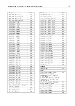
Page 11: ... 33 PSTN Account ID10 34 Radio Account ID10 35 PSTN Account ID 11 36 Radio Account ID 11 37 Parameter Address PSTN Account ID 12 38 Radio Account ID 12 39 PSTN Account ID 13 40 Radio Account ID 13 41 PSTN Account ID 14 42 Radio Account ID 14 43 PSTN Account ID 15 44 Radio Account ID 15 45 PSTN Account ID 16 46 Radio Account ID 16 47 External Line access 48 Number of Rings 49 MS Dialing Number 50 C...

Page 12: ...2 Close 109 Power Fault 110 Power Restore 111 Phone Line Fault 112 Phone Line Restore 113 Open 114 Close 115 Parameter Address Test 116 Fuse Fail 117 Fuse Restore 118 Panic 119 False Code 120 Zone 1 Alarm Report 121 Zone 2 Alarm Report 122 Zone 3 Alarm Report 123 Zone 4 Alarm Report 124 Zone 5 Alarm Report 125 Zone 6 Alarm Report 126 Zone 7 Alarm Report 127 Zone 8 Alarm Report 128 Zone 9 Alarm Rep...

Page 13: ... Restore Report 195 Zone 6 Restore Report 196 Zone 7 Restore Report 197 Zone 8 Restore Report 198 Zone 9 Restore Report 199 Zone 10 Restore Report 200 Zone 11 Restore Report 201 Zone 12 Restore Report 202 Zone 13 Restore Report 203 Zone 14 Restore Report 204 Zone 15 Restore Report 205 Zone 16 Restore Report 206 Zone Fail Report 207 Zone Fail Restore Report 208 Zone Bypass 209 Installation Service ...

Page 14: ...aracteristics byte 1 266 Zone 10 Characteristics byte 2 267 Zone 11 Characteristics byte 1 268 Parameter Address Zone 11 Characteristics byte 2 269 Zone 12 Characteristics byte 1 270 Zone 12 Characteristics byte 2 271 Zone 13 Characteristics byte 1 272 Zone 13 Characteristics byte 2 273 Zone 14 Characteristics byte 1 274 Zone 14 Characteristics byte 2 275 Zone 15 Characteristics byte 1 276 Zone 15...

Page 15: ...ns 344 Alarm Report Delay Entry Rout 345 Output Timers 346 External Siren Time 346 Parameter Address Internal Siren Time 347 Alarm Output Time 348 Anti Mask Output Time 349 Special Alarm 1 Output Time 350 Special Alarm 2 Output Time 351 Smoke Output Time 352 Fire Output Time 353 Special Fire Output Time 354 Panic Output Time 355 Silent Panic 356 Hold Up 357 Medical 358 Tamper 359 Mains Fault 360 L...

Page 16: ...ren Type 384 Relay Type 385 Smoke Type 386 ON OFF Type 387 ALARM Type 388 Audio Control Type 389 OUT 1000 1 Type 390 OUT 1000 2 Type 391 OUT 1000 3 Type 392 OUT 1000 4 Type 393 OUT 1000 5 Type 394 OUT 1000 6 Type 395 OUT 1000 7 Type 396 OUT 1000 8 Type 397 IOR 1 Type 398 Parameter Address IOR 2 Type 399 IOR 3 Type 400 IOR 4 Type 401 IOR 5 Type 402 IOR 6 Type 403 IOR 7 Type 404 IOR 8 Type 405 IOR 9...

Page 17: ...isarm 479 Siren 2 Polarity Active 480 Relay Polarity Active 481 Smoke Polarity Active 482 Parameter Address ON OFF Polarity Active 483 Alarm Polarity Active 484 Audio Control Polarity Active 485 OUT 1000 1 Polarity Active 486 OUT 1000 2 Polarity Active 487 OUT 1000 3 Polarity Active 488 OUT 1000 4 Polarity Active 489 OUT 1000 5 Polarity Active 490 OUT 1000 6 Polarity Active 491 OUT 1000 7 Polarity...

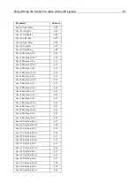
Page 18: ...Start Mins 550 User 2 Stop Hrs 551 User 2 Stop Mins 552 User 3 Start Hrs 553 User 3 Start Mins 554 User 3 Stop Hrs 555 User 3 Stop Mins 556 User 4 Start Hrs 557 User 4 Start Mins 558 User 4 Stop Hrs 559 Parameter Address User 4 Stop Mins 560 User 5 Start Hrs 561 User 5 Start Mins 562 User 5 Stop Hrs 563 User 5 Stop Mins 564 User 6 Start Hrs 565 User 6 Start Mins 566 User 6 Stop Hrs 567 User 6 Stop...

Page 19: ...616 User 5 Partition 1 8 617 User 5 Partition 9 16 618 User 6 Partition 1 8 619 User 6 Partition 9 16 620 User 7 Partition 1 8 621 User 7 Partition 9 16 622 User 8 Partition 1 8 623 User 8 Partition 9 16 624 User 9 Partition 1 8 625 User 9 Partition 9 16 626 User 10 Partition 1 8 627 User 10 Partition 9 16 628 User 11 Partition 1 8 629 User 11 Partition 9 16 630 User 12 Partition 1 8 631 User 12 P...

Reviews: