- 5 -
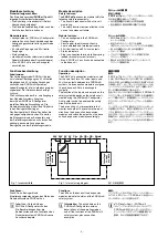
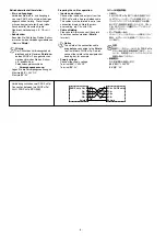
Fig. 2: PNOZ mlp montieren
Fig. 2: Installing the PNOZ mlp
図
2: PNOZ mlp
の取り付け
PNOZ ml1p links vom Basisgerät
montieren!
Install the PNOZ ml1p to the left of the
base unit!
PNOZ ml1p
をベースユニットの左側に
取り付けます。
Basisgerät und Erweiterungsmodule
verbinden
Verbinden Sie das Basisgerät und
die Erweiterungsmodule wie in den
Bedienungsanleitungen zum PNOZ m0p,
PNOZ mp und PNOZ m2p beschrieben.
• Sie können max. 4 Verbindungsmodule
PNOZ mlp links vom Basisgerät
montieren. Auf der Front des
Erweiterungsmoduls ist dies durch den
Aufdruck
symbolisiert.
• Stecken Sie keinen Abschlussstecker auf
das letzte Erweiterungsmodul.
• Montieren Sie das PNOZ mlp an die
Position wie im PNOZmulti Configurator
konfiguriert.
Achtung!
Verwenden Sie nur
Steckbrücken mit den folgenden
Bestellnummern:
PNOZ mlp: 774 639
Connecting the base unit and
expansion modules
Connect the base unit and expansion
modules as described in the operating
manuals for PNOZ m0p, PNOZ mp and
PNOZ m2p.
• You can install max. 4 PNOZ mlp
connection modules to the left of the
base unit. This is symbolised on the
front of the expansion module through the
inscription.
• Do not connect any terminators to the last
expansion module.
• Install the PNOZ mlp in the position as
configured in the PNOZmulti Configurator.
Caution!
Use only jumpers with the
following order numbers:
PNOZ mlp: 774 639
ベースユニットと
セーフティリンクモジュールの接続
PNOZ m0p
、
PNOZ mp
、
PNOZ m2p
の取扱
説明書に従って、ベースユニットとセーフティリ
ンクモジュールを接続します。
•
最大
4
台の
PNOZ mlp
セーフティリンクモ
ジュールをベースユニットの左側に取り付け
ることができます。このことは、セーフティ
リンクモジュールの前面に
記号で示さ
れています。
•
最後のセーフティリンクモジュールに終端
コネクタを接続しないでください。
• PNOZmulti
コンフィグレータでコンフィグ
レーションした位置に、
PNOZ mlp
を取り
付けます。
注意
!
次の型番の増設コネクタ以外は使
用しないでください。
PNOZ mlp: 774 639
PNOZ ml1p inbetriebnehmen
Inbetriebnahme vorbereiten:
Beachten Sie bei der Vorbereitung der In-
betriebnahme:
Achtung!
Das Erweiterungsmodul
PNOZ mlp nur im spannungslosen
Zustand ziehen und stecken.
• Für die Versorgungsanschlüsse 24
V und 0 V sind jeweils 2 Anschluss-
klemmen vorhanden. Damit kann die
Versorgungsspannung auf mehrere
Anschlüsse geschleift werden.
• Die maximale Leitungslänge zwischen
zwei Verbindungsmodulen darf max. 00 m
betragen.
• Für die Verbindung zweier PNOZ mlp
können Sie vorkonfektionierte Kabel
von Pilz verwenden. Die steckbaren
Anschlussklemmen sind wahlweise als
Federkraftklemme oder Schraubklemme
ausgeführt (siehe Zubehör).
• Verwenden Sie Leitungsmaterial aus
Kupferdraht mit einer Temperaturbe-
ständigkeit von 60/75 °C.
• Das Anzugsdrehmoment der Schrauben
auf den Anschlussklemmen finden Sie im
Kapitel "Technische Daten".
Commissioning the PNOZ ml1p
Preparing for commissioning:
Please note the following when preparing to
commission the unit:
Caution!
Only connect and
disconnect the PNOZ mlp
expansion module when the supply
voltage is switched off.
• Two connection terminals are available for
each of the supply connections 24 V and 0
V. This means that the supply voltage can
be looped through several connections.
• The maximum cable runs between two
connection modules may be max. 00 m.
• You can use ready-made cable from Pilz
to connect two PNOZ mlp. The plug-
in connection terminals are optionally
designed as spring-loaded terminals or
screw terminals (see Accessories).
• Use copper wire that will withstand
temperatures of 60/75 °C.
• The torque setting of the screws on the
connection terminals is specified in the
"Technical details" section.
PNOZ ml1p
の試運転
試運転の準備
ユニットの試運転の準備をする場合、次の点に注
意してください。
注意
!
PNOZ mlp
セーフティリンク
モジュールを接続したり取り外したり
するときには、必ず供給電圧をオフに
してください。
•
電源接続ではそれぞれ、
24 V
と
0 V
の
2
種類
の接続端子を使用できます。つまり、供給電
圧を複数の接続でループさせることができます。
•
セーフティリンクモジュール同士をつなぐ
ケーブルの長さは、最大
00 m
です。
• PNOZ mlp
同士を接続するときには、ピル
ツ製の既製のケーブルを使用できます。プラ
グイン接続端子は、ケージ式端子またはスク
リュー式端子から選択できます
(
「アクセサリ」
の項を参照
)
。
• 60/75 °C
の温度に耐えられる銅配線を使用し
ます。
•
接続端子のネジのトルク設定は、
「技術データ」
セクションに記載されています。
Summary of Contents for PNOZ ml1p
Page 9: ...Notizen Notes...
Page 11: ...11...

