


Safety
Operating Manual PSEN ml sa 1.1/2.1/2.2, PSEN ml DHM
1005457-EN-02
| 8
2
Safety
2.1
Intended use
The safety gate system is used for interlocking and guard locking swing gates and sliding
gates.
The safety gate system can be operated in two ways:
}
Unlocking with condition
The safety gate system prevents the safety gate from being unlocked while there is any
hazard within the danger zone.
}
Unlocking without condition
The operator can unlock the safety gate system at any time. After starting the unlocking,
the guard locking creates a stop command. The time required to unlock the interlocking
guard has to be longer than the time required to stop the hazardous machine function.
The hazardous machine function may only be executed under the following conditions:
}
There is a high signal at safety outputs 12 and 22 and
}
There is a low signal at safety outputs S31 (Lock/Unlock Request 1) and S41 (Lock/Un-
lock Request 2).
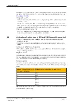
Safety inputs S31 and S41 (solenoid operation) may only be operated under the following
condition:
}
Plant is in a safe condition
Make sure that this is the case with an AND operation in the safety system immediately
before the output is operated.
The safety switch meets the requirements in accordance with:
}
EN 60947-5-3: PDDB
}
EN 62061: SIL CL 3
– EN ISO 13849-1: PL e (Cat. 4 )
}
EN ISO 14119
– Coding level with actuator PSEN ml sa 1.1: low, type 4
– Coding level with actuator PSEN ml sa 2.1/2.2: high, type 4
The safety switch may only be used with one of the approved actuators (see
The safety level PL e (Cat. 4 )/SIL CL 3 is only achieved if
}
the safety outputs use 2-channel processing
}
The solenoid has 2-channel operation via safe, tested outputs, suitable for PL e (Cat. 4)/
SIL CL 3 applications.