


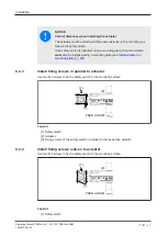


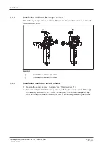


Installation
Operating Manual PSEN ml sa 1.1/2.1/2.2, PSEN ml DHM
1005457-EN-02
| 49
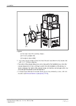
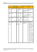
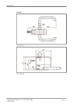
[1]
[2]
[3]
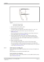
Legend
[1] Security screw of the auxiliary release
[2] Pin in the adapter disk
[3] Hexagon sockets M3x8
3. Screw the escape release with the four raised head screws M3x12 to the adapter disk
with 1,2 - 1,5 Nm (see diagram).
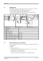
}
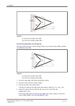
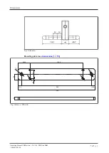
The button of the escape release pin can be removed for the installation (e.g. when the
escape release pin is to be run through a wall). Once the installation of the escape re-
lease is complete, the button of the escape release pin must be secured again with a me-
dium-strength threadlocker and hand-tightened
}
To bridge larger distances the escape release pin can be extended by a max. of 25 mm